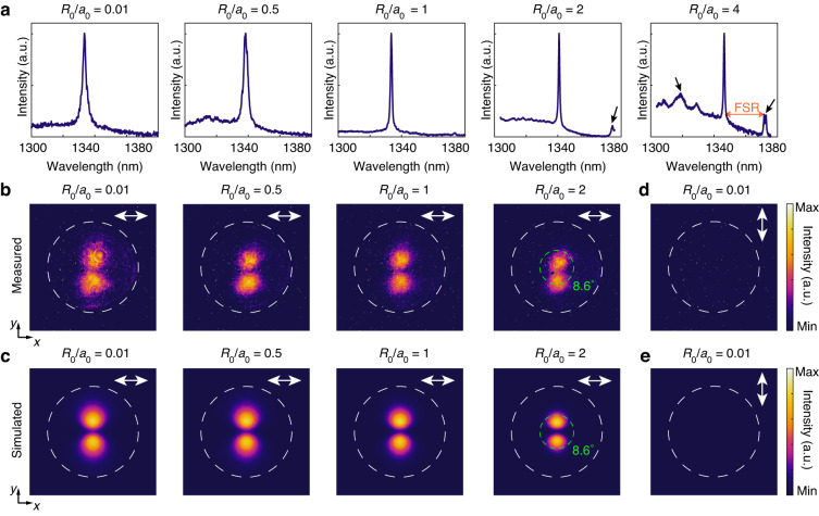
Fig. 4. Lasing characteristics of the topological Dirac-vortex microcavity lasers with different cavity sizes.
a Measured normalized lasing spectra from the Dirac-vortex lasers with R0/a0 = 0.01, 0.5, 1, 2, and 4. Some sidebands (marked by the black arrows) emerge in the lasing spectrum of the device with R0/a0 = 2 and 4. The FSR is determined by the distance between the desired lasing peak and the undesired sidebands in the lasing spectrum. b, c Measured (b) and simulated (c) x-polarized far-field emission patterns from the Dirac-vortex lasers with R0/a0 = 0.01, 0.5, 1, and 2. Increasing R0 leads to a decreased divergence angle. The Dirac-vortex laser with R0/a0 = 2 exhibits a half width at half maximum of the emission beam of 8.6°, as marked by the green dashed circles in b and c. d, e Measured (d) and simulated (e) y-polarized far-field emission patterns from the Dirac-vortex laser with R0/a0 = 0.01. The white double-headed arrows in b–e indicate the polarization direction for the corresponding far-field emission pattern. The white dashed circles in b–e indicate the numerical aperture (NA = 0.43) of the 50× collecting objective

