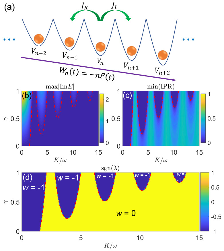
Figure 9.
Floquet NHQC under high-frequency driving forces [264]: (a) Schematic diagram of the driven lattice model. (b) The maximal imaginary parts of quasienergies, (c) the minimal values of IPRs, and (d) the signs of Lyapunov exponents of the Floquet NHQC in Equation (169). Other system parameters are , , and the length of lattice is . The red dashed line in each panel denotes the boundary between extended phase (with complex quasienergies) and localized phase (with real quasienergies), which satisfies the condition in Equation (171). The topological winding number w of each phase is denoted explicitly in (d).

