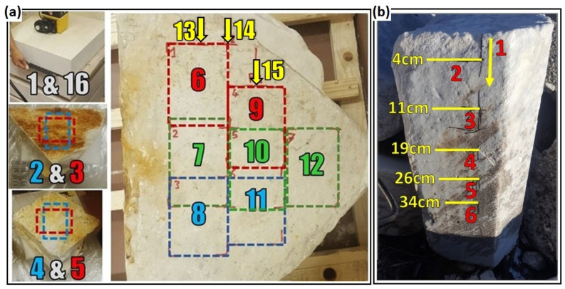
Figure 4.
(a) The positions of the GPR antenna for different measurements performed in the laboratory. Records 1 and 16 were surveyed on marble blocks of Botticino for amplitude calibration at the beginning and end of each experiment. Records 2 and 3 were surveyed from the central position of the small blocks of Carrara (see Figure 1a, left). The antenna was rotated 90 degrees from record 2 to record 3. Similarly, records 4 and 5 were surveyed from the central position of the medium blocks of Carrara (see Figure 1a, right). Records 6 to 12 were surveyed on the large blocks of Carrara (see Figure 1b) by deploying the antenna at the fixed positions from 6 to 12. Profiles 13, 14 and 15 were recorded as continuous profiles parallel to the longer side of the blocks by moving the antenna from the positions 13, 14, and 15. (b) Measurements on the Carrara marble block with natural fracture used for field test (see Figure 2b). Profile 1 was recorded as a continuous profile from top to down. Records 2 to 6 were surveyed by placing the antenna at the positions 2 to 6, and yellow numbers are the distances of the antenna’s positions from the top of the block.

