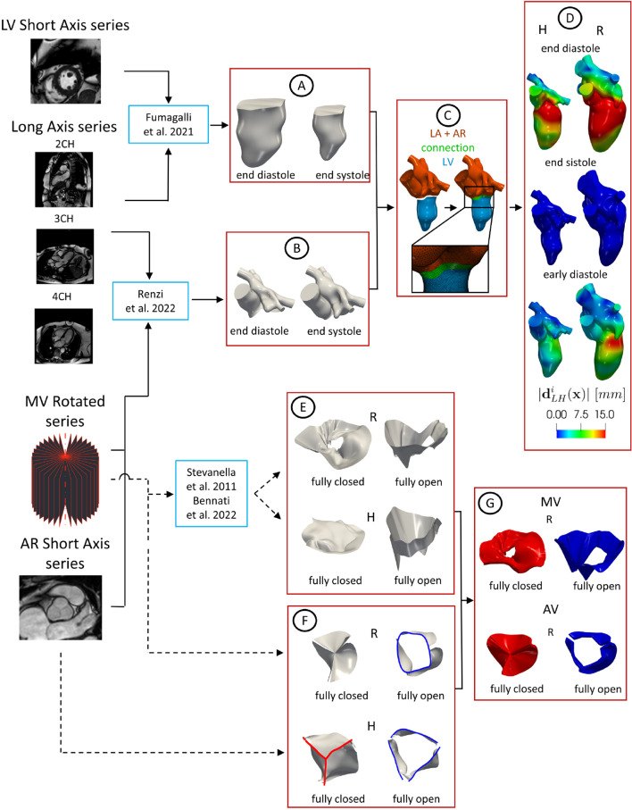
Fig. 1.
Flowchart to reconstruct the geometries of LH and valves and their displacements. Continuous lines refer to the steps followed to reconstruct the LH walls and the dashed lines to the reconstruction of the valves. A: Geometric reconstruction of the LV endocardium for all the 30 frames by adopting the strategy described in Fumagalli et al. (2022) (here we reported the geometries at two representative frames as an example). B: Geometric reconstruction of AR and LA for all the 30 frames by adopting the strategy proposed in Renzi et al. (2022) (two representative frames reported as an example). C: Creation of a connection to merge LV with AR and LA to obtain the final LH geometry. D: Registration of the displacement field with respect to the end systolic configuration (magnitude of reported at three representative frames as an example). E: Geometric reconstruction of MV in the fully open and closed configurations by adopting the method proposed in Stevanella et al. (2011). F: Geometries of AV in the fully open and closed configurations obtained by adaptation of zygote geometry to the annulus segmented from the cine-MRI in the closed (red) and open (blue) frames, respectively. Notice that the annulus of the closed AV of patient R was obtained through algorithms based on the closest point distances (Fedele and Quarteroni 2021). G: Valve configurations after the extrusion needed for the resistive numerical method (we reported as representative case only patient R)

