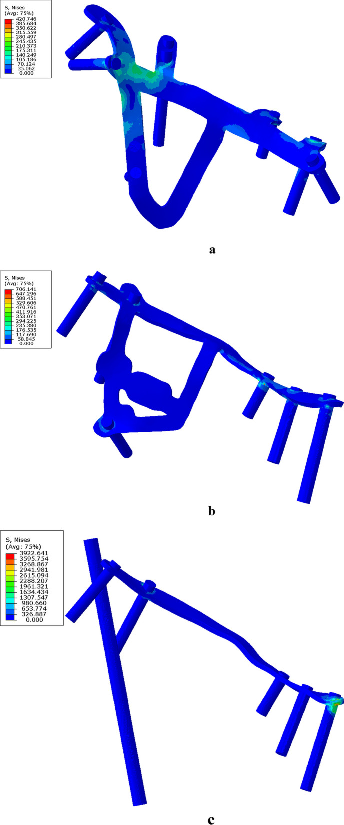
Fig. 2.

Hip joint abduction at 45° is used as an example to illustrate the stress and displacement nephogram of each model under external force. a Stress nephogram of the Bespoke 3D-printed titanium alloy plates’ model. The maximum stress distribution is at the junction of the posterior column and the inner arcuate line. b Stress nephogram of the Union Plate, with maximum stress located at the screw in the middle of the superior pubic ramus. c Stress nephogram of a common reconstruction plate. The maximum stress is distributed at the end of the plate near the pubic symphysis
