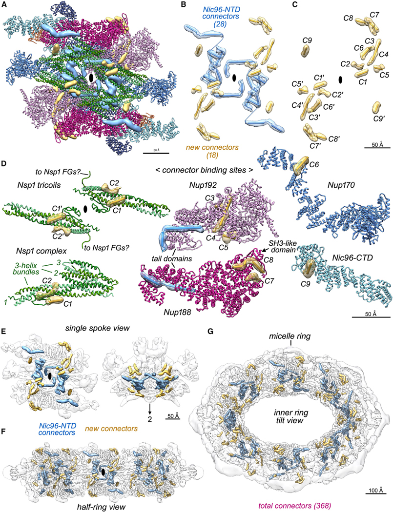
Figure 3. Connectors in the inner ring tie together Nup layers in the spoke.

(A) A front view of the spoke with Nups displayed as ribbons and connectors as segmented and color-coded density maps: Nic96 NTD connectors (blue) and new connectors in gold.
(B) A front view is shown along the local 2-fold axis (black ellipse) with spoke connectors as cylinders and strands in their local density.
(C) Newly identified and grouped connectors labeled C1 to C9 (and their symmetry mates: C1′–C9′) start at the inner layer and extend into the membrane-interacting layer (Table S3).
(D) Interactions between new connectors (gold) and their Nup partners.
(E) Color-coded electron density for Nic96 NTD and new connectors are shown for a single transparent spoke (front and top views).
(F) All inner ring connectors are shown in a half ring view.
(G) Connectors within the inner ring are viewed in a 45° tilt view.
