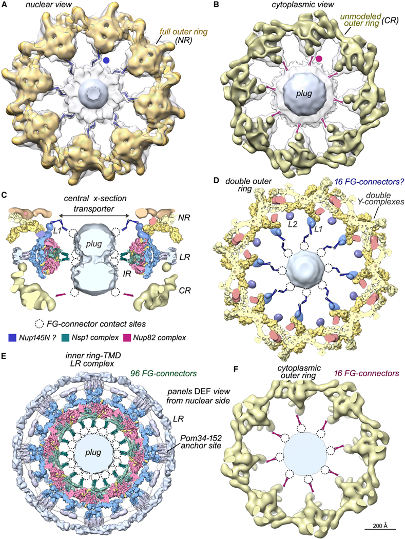
Figure 6. Bridging FG connectors between the core scaffold and central transporter.

(A) A map of the full nuclear double outer ring (gold, NR) is docked within a density map from the entire NPC (transparent gray). A thick slab shows connectors from the double outer ring to the central transporter/plug (blue dot), which were modeled with blue rods for visualization.
(B) A map of the single cytoplasmic outer ring (bronze, CR) is docked into a map of the entire NPC. This view reveals FG connectors (red dot and rods) appropriately positioned to originate from the Nup82 complex associated with the single outer ring.
(C) Modeled FG connectors are present at three levels along the central channel in this central cross-section; labels: inner ring (IR), lumenal ring (LR), and linker domain 1 (L1). Possible contact sites on the plug (dotted circles) and a color key for FG connectors are shown.
(D) A thick section of the double outer ring viewed along the central C8 axis with modeled FG-connector bundles to the central transporter. (D)–(F) are viewed from the nuclear side.
(E) Thick section of the inner ring-TMD lumenal ring complex with modeled FG connectors from Nsp1 complexes.6,7
(F) Thick section of the cytoplasmic outer ring with modeled FG connectors.
