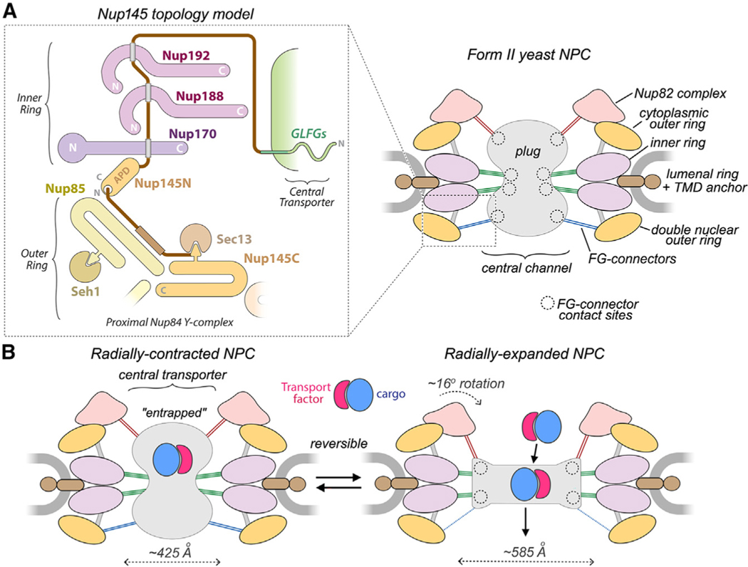
Figure 7. Nup145 topology diagram and interplay between the core scaffold and central transporter/plug.
(A) Left: proposed Nup145 topology with a region of the double outer ring shown as an outset in the dashed box from the right-hand panel. Nup145N binding sites are indicated by gray rectangles. Right: schematic model of the form II yeast NPC with FG connectors to the plug/central transporter and their contact sites (dashed circles).
(B) Radial expansion of the NPC scaffold may trigger functional changes in the central transporter. FG connectors appear to be maintained in the transition; connectors are color-coded (Figure 6C) based on location and possible Nup anchor. Left: transport factors with cargo may be entrapped within the FG mesh of the plug-like transporter. Right: reorganization of the core scaffold and FG mesh promotes translocation of transport factor-cargo complexes.

