. 2023 Oct 24;52(22):7848–7948. doi: 10.1039/d0cs00936a

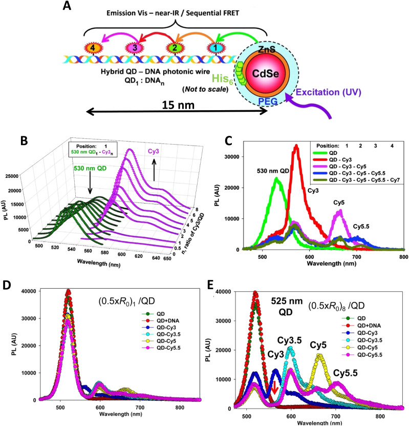
Fig. 17. Hybrid QD-DNA linear wires. (A) (His)6-modified DNA backbone self-assembled to the QDs via metal-affinity coordination. The resulting structure consists of a central QD with multiple, rigid dye-labeled DNA centro-symmetrically arrayed on its surface as designated by the QD1 : DNAn ratio. UV excitation of the system results in an energy transfer cascade from the central QD through the sequential aligned dye-acceptors. 1–4 indicate sequential dyes and are used to indicate dye position relative to the QD. (B) Deconvoluted PL spectra from 530 nm QD donors self-assembled with an increasing ratio of (His)6-peptide-DNA with Cy3 acceptor located in position-1. (C) Composite PL spectra from 530 nm QD donors self-assembled with unlabeled DNA, DNA with Cy3 in position-1, Cy3 in 1/Cy5 in 2, Cy3 in 1/Cy5 in 2/Cy5.5 in 3, Cy3 in 1/Cy5 in 2/Cy5.5 in 3/Cy7 in 4. Panels A-C reproduced with permission from ref. 126 Copyright 2010 American Chemical Society. Representative FRET progression in second generation QD-DNA constructs where the QD displays 1 fully dye-loaded wire (D) or 8 full wires (E). FRET acceptors are placed on the wires with 0.5 × R0 inter-dye spacing. Green and red curves correspond to the emission spectrum of DHLA-PEG coated QDs alone and then in the presence of just 1 non-labeled DNA wire. Panels D, E reproduced with permission from ref. 241 Copyright 2013 American Chemical Society.

Fig. 17