. 2023 Oct 24;52(22):7848–7948. doi: 10.1039/d0cs00936a

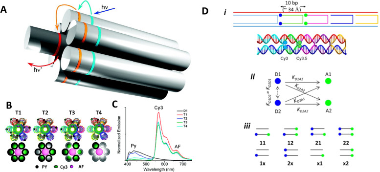
Fig. 21. Seven-helix DNA bundle hosting cyclic arrays of three chromophores and dual rail structure. (A) Schematic of the self-assembled 7-helix bundle (7HB) nanoscaffold containing three distinct arrays of chromophores: the primary D, the intermediate relay R, and the A, represented by the cyan, orange, and red rings, respectively. Upon excitation of the primary D array, a stepwise energy transfer cascade occurs. The distance (along the helical axes) between the dyes in adjacent arrays is 3.5 bps. (B) Schematic representation of each triad. The black spheres, dark green ovals, and pink spheres represent Py, Cy3, and AF, respectively. A simplified representation of each triad is also shown below the corresponding helical schematic, where the colored circles represent the presence of the dye molecules on the DNA helices. Triads 1–4 contain ratios of 6 : 6 : 1, 6 : 3 : 1, 3 : 6 : 1, and 1 : 1 : 1 of the Py, Cy3, and AF dyes, respectively. (C) Normalized emission spectra of D1 and T1–T4, all with excitation at 380 nm. Reproduced with permission from ref. 251 Copyright 2011 American Chemical Society. (D) i – Upper: Dual rail structure schematic self-assembled from seven DNA oligos. Cy3 and Cy3.5 positions at the ends of hairpin oligos indicated by solid blue circles and solid green circles, respectively. One Cy3 attached using a 3-carbon linker, while the other Cy3 uses a 6-carbon linker. Cy3.5s are each attached using a 3-carbon linker. Lower: Schematic of the dual rail DNA structure showing the double crossover motif and dye positioning. ii – Putative ET pathways from Cy3 (solid blue circles) and Cy3.5 (solid green circles). The solid black arrows indicate D–A hetero-FRET and dashed black double arrow is a homo-FRET coupling between the two Ds. iii – Schematics of the FRET structures and control structures. Reproduced with permission from ref. 160 Copyright 2016 American Chemical Society.

Fig. 21