. 2023 Oct 24;52(22):7848–7948. doi: 10.1039/d0cs00936a

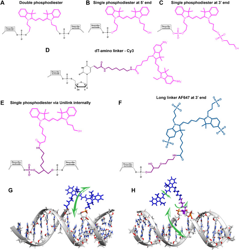
Fig. 6. Representative DNA–dye conjugation strategies. (A) Double phosphodiester linkages (at 3′ and 5′ ends) for internally coupling a Cy3 dye (pink) for instance – to the oligonucleotide phosphate backbone. (B) End-coupling the Cy3 to the 5′ end of the oligo. (C) End-coupling a Cy3 to the 3′ end of the oligo. Note, often the 3′ end-coupled dye could have an addition C3 spacer group on the non-attached propyl chain that supports attachment to the CPG bead during synthesis. (D) Internally- or end-coupling Cy3 via a C6 amide linkage onto an amine-modified dT nucleotide. This labeling would usually occur post-synthesis using a N-hydroxysuccinimide (NHS-ester) activated version of the dye. (E) Internally coupling the dye but using a short C3 amide linkage and single point of dye attachment to an amine inserted into the DNA during synthesis. This would also be post-synthesis. (F) Internally coupling a different dye – Alexa Fluor 647 (indigo) to an amine on a linker inserted during synthesis – but using a longer linker. (G) The double phosphodiester linkage will severely restrict rotational motion in the dye – Cy5 (blue). (H) A single phosphodiester linkage allows for far more rotation about the linkage as well as along the polymethine bridge of Cy5. The former could promote dye interaction with the major groove while the latter could lead to photoisomerization.

Fig. 6