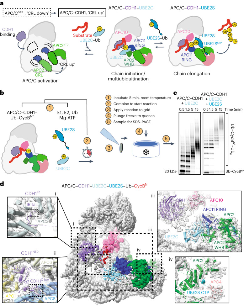
Fig. 1. TR-EM reveals structure of APC/C–CDH1–UBE2C–UBE2SCTP during substrate polyubiquitination.
a, Cartoon representation of reaction cycle carried out by the APC/C as it ubiquitinates substrates. The transition from the ‘CRL (cullin–RING) down’ inactive conformation to the ‘CRL up’ active conformation is facilitated by coactivator binding. Initiation of ubiquitination on target substrates is carried out by the recruitment of UBE2C~Ub by the APC2 WHB (winged-helix B) and APC11 RING domains. UBE2S elongates chains initiated by UBE2C. b, Overview of TR-EM approach. Two mixtures containing the reaction components are incubated at room temperature (1). The mixtures are combined to start the reaction (2). Samples are taken from the reaction at timepoints indicated and applied to a grid (3) that is then plunge frozen (4) and imaged using cryo-EM. Representative samples were taken at the time the grids were plunge frozen for SDS–PAGE (5), shown in c. c, Fluorescent monitoring of an SDS–PAGE gel showing APC/CCDH1-E2 (UBE2C or both UBE2C and UBE2S)-dependent substrate modification at each timepoint for which a grid was frozen. At least three experimental replicates were repeated to optimize conditions. Uncropped gel image available in source data. d, 3D reconstruction of particles from the filtered APC/C–CDH1–UBE2C–UBE2S dataset at 3.5 Å showing the active catalytic architecture assembled. Atomic models of key subunits and ubiquitination components fitted into the cryo-EM density, including CDH1 bound to the APC/C scaffold (i and ii), UBE2C clamped by the APC2 WHB and APC11 RING domains (iii), and the UBE2S CTP bound to the groove formed by APC2 (green) and APC4 (light pink) (iv).

