
Fig. 2.
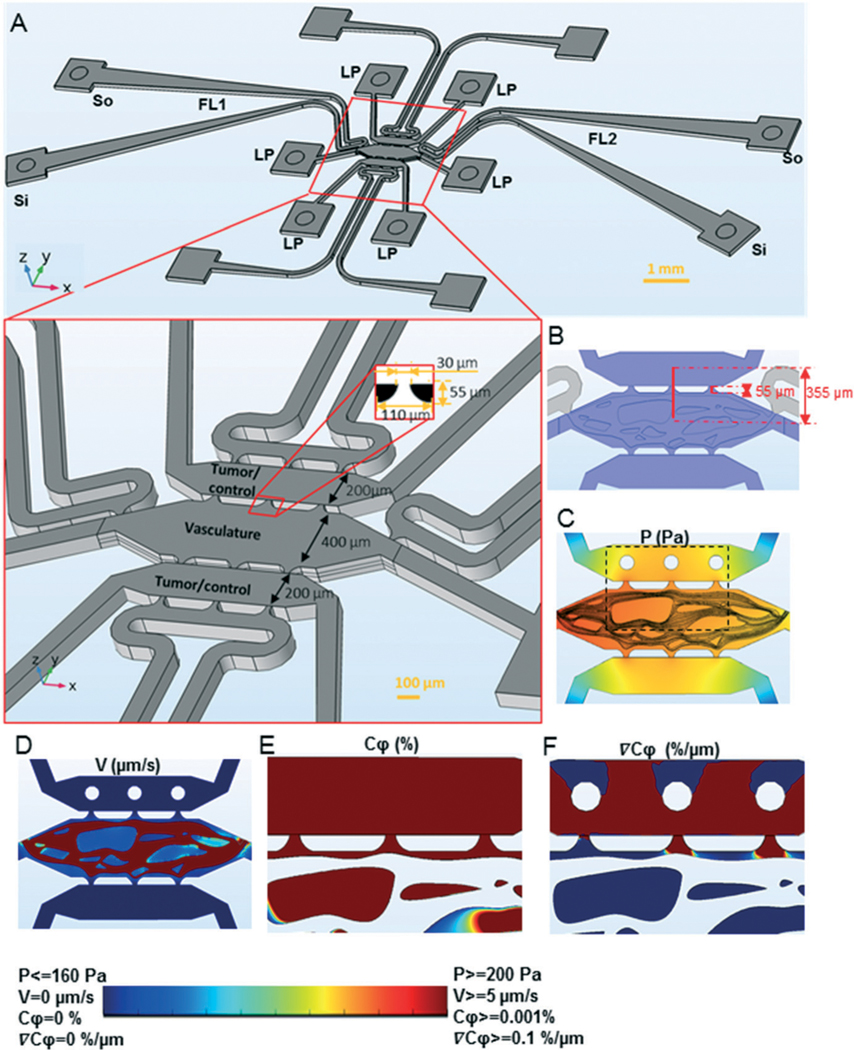
The convection–diffusion model for tumor-vascular communication in the device. A) The device design showing three parallel tissue chambers, each of which is connected to two square tissue loading ports (LP). The tissue chambers are separated by a microporous wall (bottom insert) with a pore design shown in the 2D insert (black is PDMS and white is empty chamber space). The central tissue chamber is for the microvasculature and the two side chambers are for loading tumor or control tissues. The microvascular chamber is attached to two dedicated fluidic lines (FL1 and FL2), which are connected to sources and sinks (so and Si) of their own. The hydrostatic pressure-drop between so and Si drives fluid flow through the fluidic lines, and the hydrostatic pressure drop between the fluidic lines drives flow through the vasculature chamber. Each of the side chambers are attached to a dedicated fluidic line (white), which serves as a sink for excess fluid drainage. B) The device design showing three parallel tissue chambers (blue). The distance between the centers of the top and the central tissue chambers and the length of pore is also indicated. C)–F) A 3D model of microvasculature (central tissue chamber) and tumors (top tissue chamber) was constructed with average pressure drop of 10 mm H2O across the central microvascular and side tissue chambers. The pressure (C) and velocity (D) profiles at the vertical center of the device are shown. The concentration (E) and concentration gradient (F) profiles at the vertical center of the device for an area of the tissue chambers, indicated by the rectangle in C, are shown. The rainbow color scale with the corresponding upper and lower limits of the variables plotted in C–F.