Figure 2.

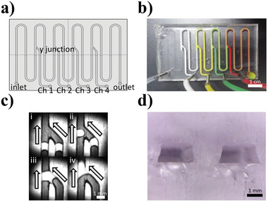
Digitized DCF system. a) Schematic diagram representing the four y‐junction channels in the DCF chip. b) Image of the DCF chip. c) Microscopy images of droplet association. d) Cross‐sectional image of the channels.

Digitized DCF system. a) Schematic diagram representing the four y‐junction channels in the DCF chip. b) Image of the DCF chip. c) Microscopy images of droplet association. d) Cross‐sectional image of the channels.