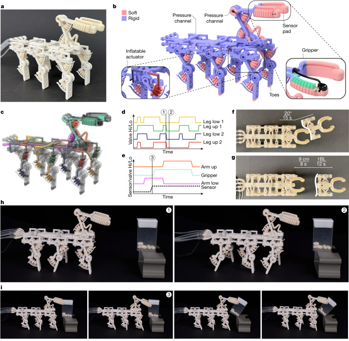
Fig. 4. A locomoting, sensing and grasping robot that is functional after 3D printing.
a, A pneumatically actuated soft-rigid hybrid robot printed with an all-in-one process. b, Rendered illustration of the robot with rigid parts shown in blue and soft parts visualized in pink. A zoom-in onto the gripper element is shown with the chamber structure visible (green). The sensor pad’s cavity and signal line are shown in black. The two-jointed leg of the robot is in the relaxed position with the upper actuator’s channel structure in red and the lower channel in blue. c, An illustration of the four pneumatic networks used for the locomotion of the robot. The colour code for the channels is shown in d for the channels related to gait and in e for grasping. d, Actuation pattern of the four chambers used for locomotion. During initialization, all actuation channels are pressurized. After initialization, the gait cycle starts once ‘Leg low 1’ is pressurized for a second time. Two states of the gait indicated by the vertical lines labelled ‘1’ and ‘2’ are illustrated in h. The gait cycle repeats once ‘Leg low 1’ is pressurized again for a third time. e, The actuation patterns for a grasp are indicated with solid lines and the pressure in the sensor pad is indicated by a dashed line. The closed gripper state is indicated by the vertical line labelled ‘3’. The control logic would depressurize the gripper system if the pad’s sensor signal is below a threshold (that is, contact is not detected). Given that contact is detected for the example in ‘3’, the gripper is commanded to lift the grasped object. f, Visualization of the robot’s ability to turn. g, The robot’s speed when locomoting. h, Still images of the gait states ‘1’ and ‘2’ as illustrated in d with the change in leg position visible. i, Sequential still images of the grasp procedure with contact detection in ‘3’, as illustrated in e.

