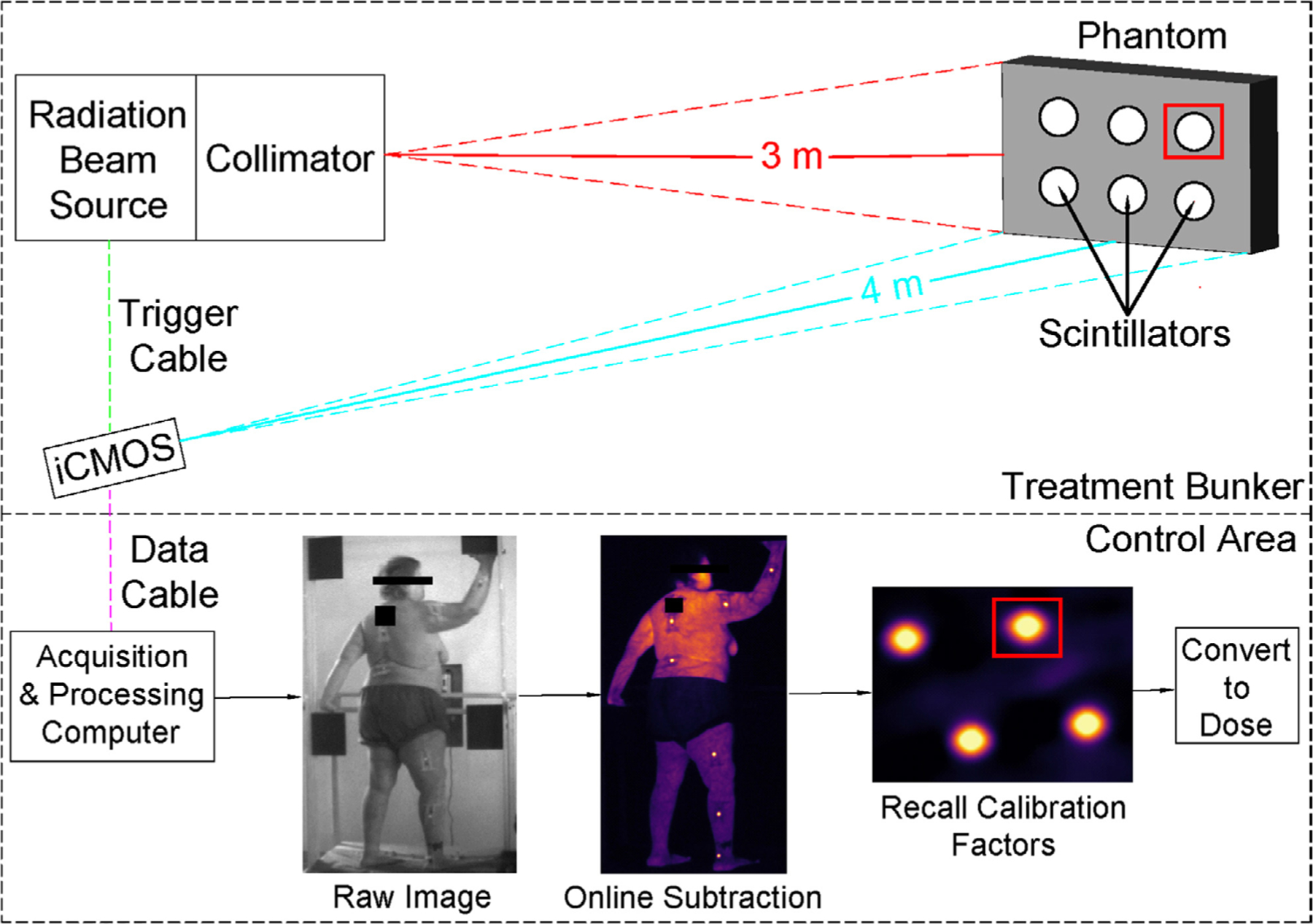
Figure 1.

An illustration of the TSET imaging setup. The linac is represented by the ‘radiation beam source’ and corresponding ‘collimator’. Image acquisition is time-gated to linac pulses; thus, a triggering cable is attached between the signaling panel of the linac and the camera (‘trigger cable’). Image data is sent to a computer located outside of the treatment bunker via optical data cable. Overview of internal image processing steps is shown in ‘control area’ panel. Sample ROI are shown as red squares.
