
Figure 3.
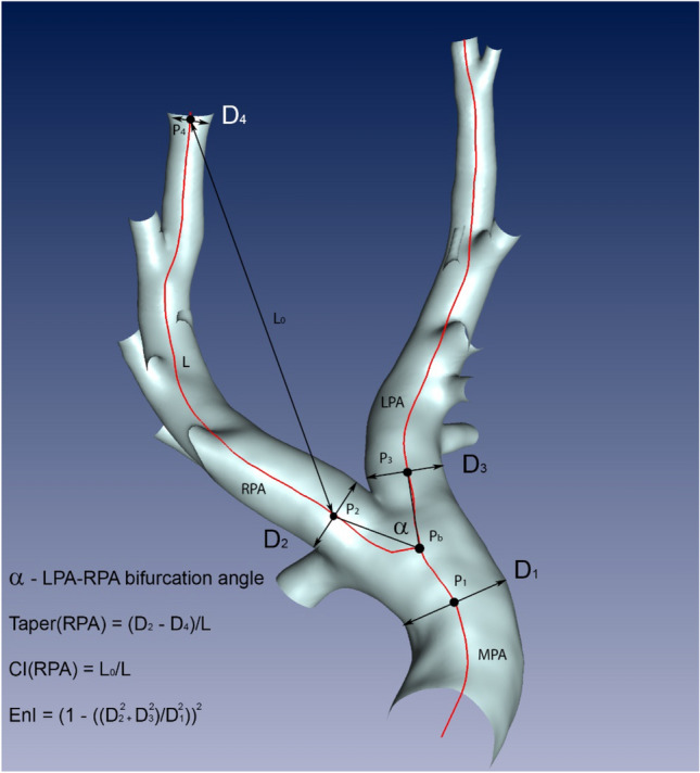
Measurements obtained from the centreline-based analysis: the centreline (red) is subdivided into several vertices, connected by edges. For each vertex the vessel diameter is available. The vertices P2 and P4 are used for the measurement of the length L, the curvature index (CI) in the RPA using the lengths L and L0, and the RPA taper using the diameters D2 and D4. L0 is the direct distance (black line with arrows) between vertices P2 and P4, whereas L is the length of the curved centreline (red line) connecting the same vertices. The vertex Pb marks the LPA-RPA bifurcation node. The marked vertices P1, P2 and P3 are located at the distance of 10 mm from the bifurcation vertex. Diameters measured at these vertices are used to measure the enlargement index EnI. The bifurcation angle α between LPA and RPA is the angle between the vectors (black lines) connecting the Pb with P2 and P3.