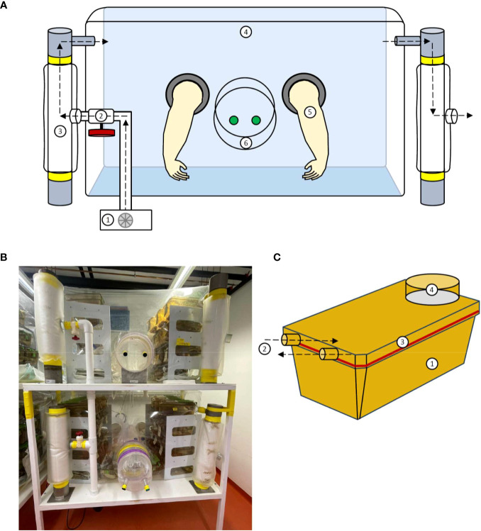
Figure 1.
Structure of a flexible film isolator and the ISOcage P. (A) Schematic view of the isolator construction including the 1. Blower; 2. Air valve; 3. Filter column; 4. Isolator shell; 5. Gloves and 6. Isolator port closed with caps from in- and outside. (B) Photograph of a flexible film isolator. (C) Schematic view of the ISOcage P system with 1. Cage, 2. Air in- and outlet connecting to cage rack, 3. Hermetically sealed lid and 4. HEPA air filter (Tecniplast ISOcage P system). Air flow is depicted by dotted arrows.

