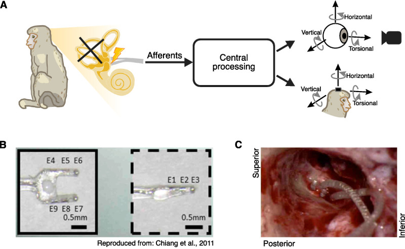
FIG. 1.

Implantation of vestibular prosthesis stimulating electrodes after prior labyrinthectomy. (A) Diagram of the vestibular pathways and the behavioral outputs. Top: 3D videooculography of the evoked eye movement (mediated via the VOR). Bottom: 3D gyroscope measurement of the evoked head movement (mediated via the VCR). (B) Electrode array image. Reproduced from Chiang et al. (13). (C) Photo of the inner ear during electrode implant surgery. The two-pronged array is on the left while the single-pronged array is on the right.
