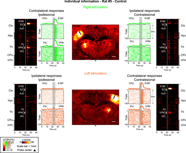
Figure 3. Early post-stroke alteration of whisker-to-barrel thalamocortical circuit.
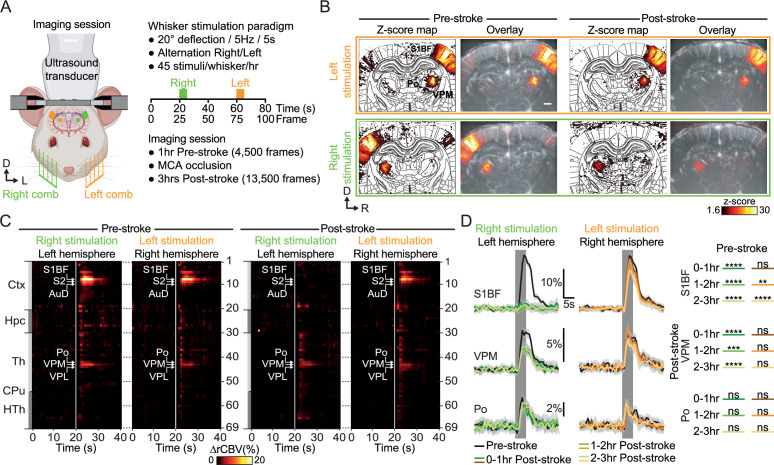
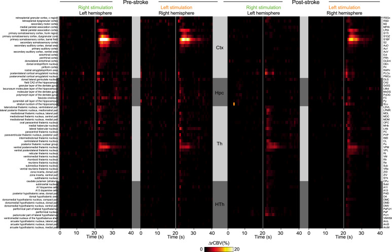
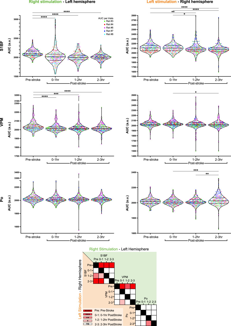
(A) Front view representation of functional ultrasound (fUS) imaging during repetitive stimulation of the left (orange) or right whisker pad (green) with a mechanical comb in awake head-fixed rats. Whisker stimulations were delivered alternately between left and right whisker pads before and early after MCA occlusion (MCAo). Each rat receives 45 stimuli per whisker pad each hour of imaging. (B) Average activity maps (z-score) from one rat depicting evoked functional responses to either left (orange) or right whisker pads stimulation (green) registered with a digital version of the rat Paxinos atlas (white outlines) and overlaid with the corresponding coronal µDoppler image, before (left; Pre-stroke, average of 45 trials) and after stroke induction in the left hemisphere (right; Post-stroke, average of 125 trials). (C) Region-time traces of the average hemodynamic changes (∆rCBV (%)) in response to right (green) or left whisker stimulation (orange) extracted from the contralateral hemisphere (left and right, respectively) before (left; Pre-stroke, n=5, 45 trials/rat) and after stroke induction in the left hemisphere (right; Post-stroke, n=5, 135 trials/rat). Brain regions are ordered by major anatomical structures (see Supplementary file 2). The vertical line represents the stimulus start. S1BF, S2, AuD, VPM, VPL, and Po regions are brain regions significantly activated (all pvalue <0.01; GLM followed by t-test). A larger version of panel C is provided in Figure 3—figure supplement 2. (D) Left, Average response curves from the S1BF, the VPM, and Po regions before (Pre-stroke, black, n=5, 45 trials/rat), and from first to third hour after stroke induction (0–1 hr, 1–2 hr, 2–3 hr Post-stroke, orange and green, n=5, 45 trials/hr/rat). Data are mean ± 95% CI. The vertical bar represents the whisker stimulus. Right, Statistical comparison of the area under the curve (AUC) between pre-stroke and post-stroke response curves for S1BF, VPM, and Po regions (Non-parametric Kruskal-Wallis test corrected with Dunn’s test for multiple comparisons; ns: non-significant; *p<0.05; **p<0.01; ***p<0.001; ****p<0.0001. See also Figure 3—figure supplement 3). Scale bars: 1 mm. D: Dorsal; L: left; R: right; Ctx: Cortex; Hpc: Hippocampus; Th: Thalamus; CPu: Caudate Putamen; HTh: Hypothalamus; S1BF: barrel-field primary somatosensory cortex; S2: Secondary somatosensory cortex; AuD: Dorsal auditory cortex; VPM: Ventral posteromedial nucleus of the thalamus; VPL: Ventral postero-lateral nucleus of the thalamus; Po: Posterior nucleus of the thalamus.
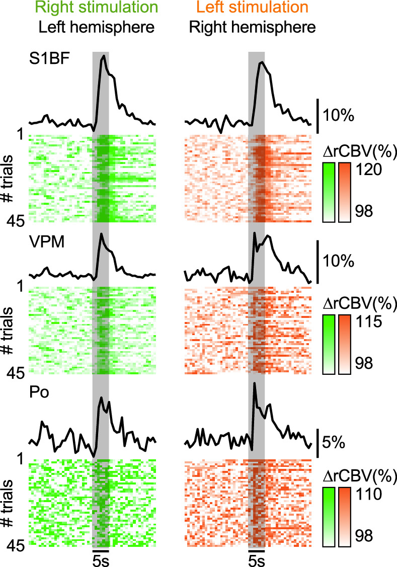
Figure 3—figure supplement 1. Averaged hemodynamic response curves (∆rCBV in %) of 45 consecutive right (green) or left whisker stimulation (orange; 1 hr recording) extracted in the contralateral S1BF, VPM, and Po regions (top to bottom).
