Fig. 3.
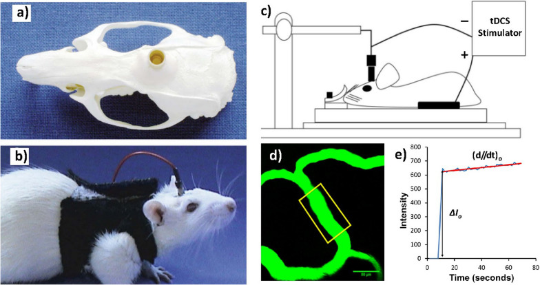
Electrode arrangement for transcranial DC stimulation in a rat. a The epicranial electrode (contact area = 3.5 mm2) is fixed onto the skull unilaterally above the frontal cortex (1.5 mm right and 2 mm anterior to bregma) using dental cement. b Before DC stimulation, the epicranial electrode is filled with saline solution. A large rubber plate mounted on the chest serves as the counter electrode, images adapted from Liebetanz et al. [104]. c Schematic of the setup for the tDCS. One electrode connects to the rat cranium and the counter electrode connects to the ventral thoracic region, d Determination of the BBB solute permeability with illustration of the scanning region of interest (ROI) comprising several microvessels. The yellow frame enclosed area is the ROI used to determine the BBB permeability to a solute. e Total fluorescence intensity in the ROI as a function of the perfusion time. Fluorescence intensity in the figure is proportional to the total amount of solute accumulating in the region surrounding the microvessel. Figure taken from Shin et al. [101]

