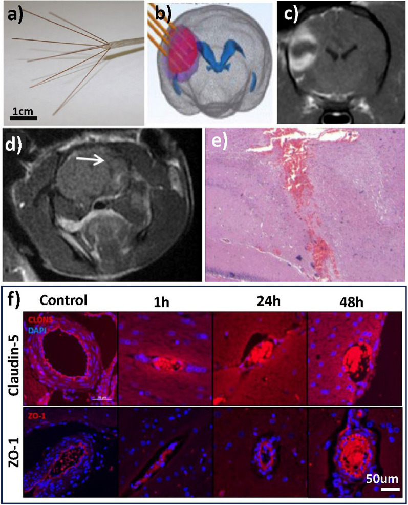
Fig. 4.
HFIRE stimulation, where a illustrates the distal end of the CETCS system with microneedles arborized from the primary cannula in convection-enhanced delivery CED catheters. b Schematic needle insertion in HFIRE induced BBB disruption and c post-contrast MRI images after gadolinium enhancement surrounding tumour area after treatment. Figures taken from Partridge et al. [119]. d MRI analysis of control brains in electroporation treatment with visible needle path (white arrow) obtained 30 min post treatment and e Histopathology of brain region with minimal bleeding along electrode insertion path. Figures taken from Sharabi et al. [61]. Immunofluorescent staining of transverse brain samples following intracranial HFIRE revealed a deceased in claudin-5 and ZO-1 reactivity 1 h post-treatment followed by gradual increase over time compared to control. Scale bar is 50 µm across all images. Image taken from Partridge et al. [118]

