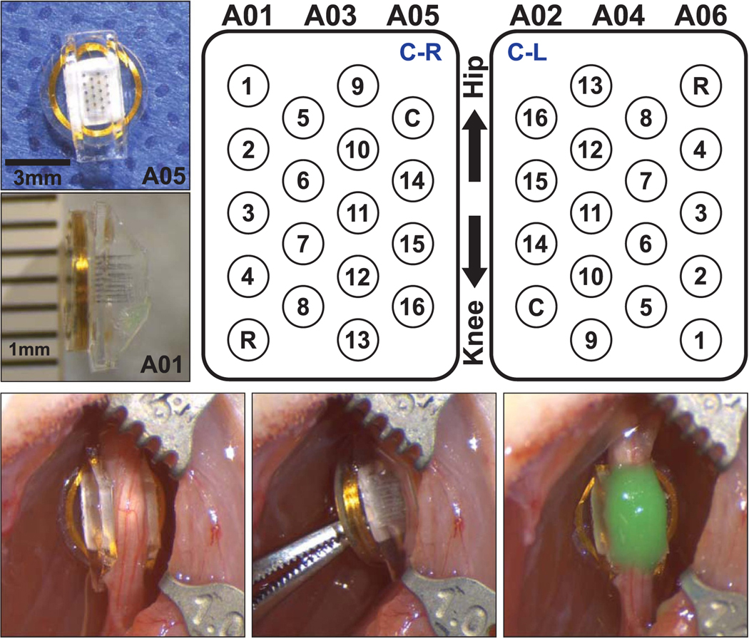
Figure 1.

(Top left) Images of the WFMA device before implantation in animal A05 and after explant from animal A01. (Top right) Electrode array layout showing device orientations ‘C-R’ and ‘C-L’ when implanted on the nerve as viewed from above, looking down into the silicone channel. Locations of the reference and counter electrodes are indicated by R and C, respectively. (Bottom) WFMA device in the left sciatic nerve of animal A06 after inserting the electrodes and after securing the WFMA with silicone sealant (Kwik-Cast™).
