
Fig. 3. Dynamics of electromechanical coupling of multi-directional anisotropic cardiac tissues.
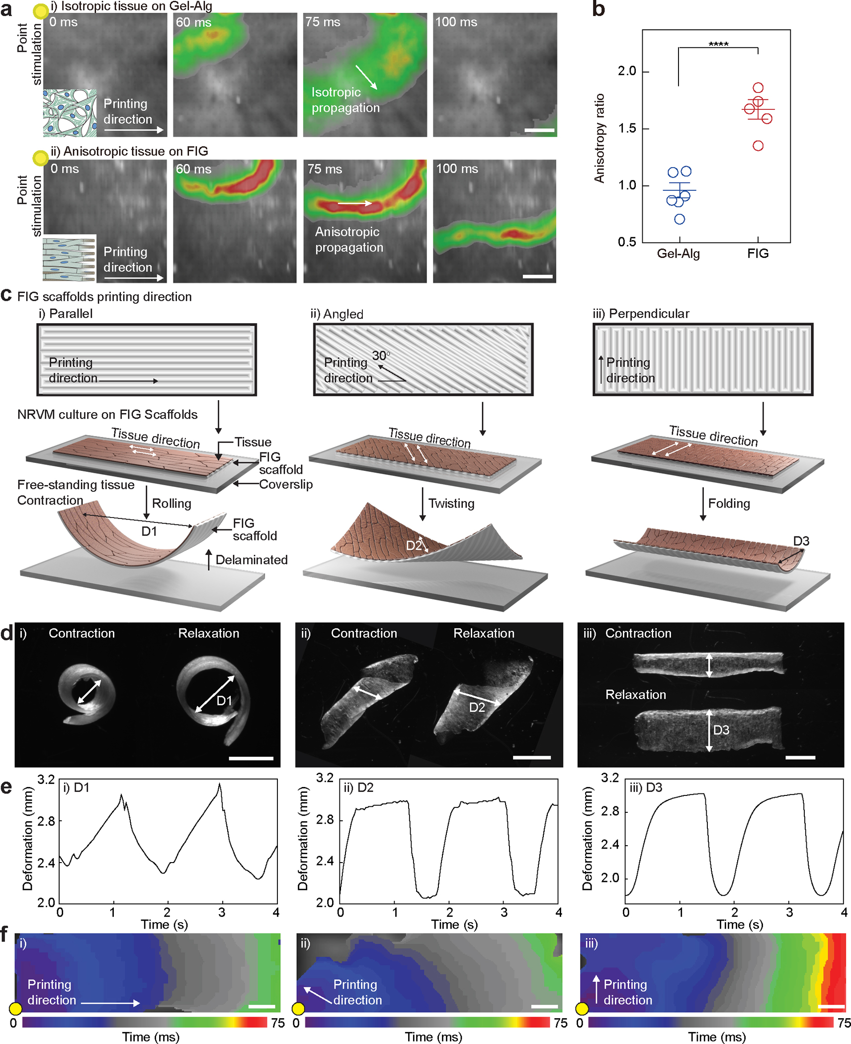
a, Representative Ca2+ transient propagation images from Ca2+ optical mapping of NRVM tissues cultured on Gel-Alg scaffolds (i) and FIG scaffolds (ii), resulting in isotropic (i) and anisotropic (ii) Ca2+ propagation, respectively, under 1 Hz point electrical stimulation at the top-left corner (yellow dot). Scale bar, 2 mm. b, The anisotropy ratio () for NRVM tissues on Gel-Alg scaffolds and FIG scaffolds, quantifying anisotropic Ca2+ propagation. Statistical analysis was performed using a two-tailed student’s t-test with unequal variance. ****P = 0.000174. n=6,5 tissues per scaffold condition. Data are presented as mean values +/− SEM. c,d, Schematic illustration (c) and microscope images (d) of NRVM tissue cultured on rectangular shaped FIG scaffolds printed in parallel (i), angled (ii), and perpendicular (iii) direction to the long side of scaffold geometry. Delaminated free-standing tissue layers from the coverslip showed different contractile motions, rolling (i), twisting (ii), and bending (iii). Scale bar, 2mm. e, Diameter (arrow in (d)) of the deformed shape continuously changes in time under 0.5 Hz field electrical stimulation. f, Isochrone mapping images demonstrating Ca2+ propagation of NRVM tissues on parallel (i), angled (ii), and perpendicular (iii) patterned FIG scaffolds. Point electrical stimulation at 1 Hz (yellow dot) initiates Ca2+ propagation, showing fast propagation in parallel and angled patterns but slow propagation in the perpendicular pattern throughout the scaffold geometry. Scale bar, 1 mm