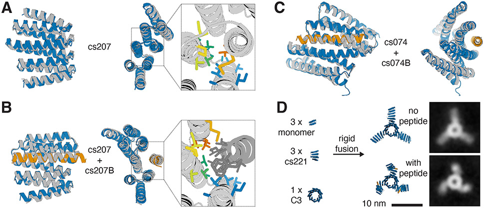
Figure 3: Close agreement between crystal structures and design models for both designed states.
A) Design model (blue) of hinge cs207 in state X overlaid with crystal structure (gray) of hinge cs207 crystallized without peptide. Right panel shows a close-up view of the side chains in the interface between the two hinge domains (side chain colors follow a spectrum from blue to red from N- to C- terminus). B) Design model (hinge in blue, peptide in orange) of the cs207 state Y hinge-peptide complex overlaid with crystal structure (gray) of hinge cs207 co-crystallized with peptide cs207B. Right panel shows a close-up view of the side chains in the interface between hinge and peptide (hinge side chain colors match the corresponding side chains in A, peptide side chains are shown in dark gray). C) Design model (hinge in blue, peptide in orange) of hinge cs074 in state Y overlaid with crystal structure (gray) of hinge cs074 co-crystallized with peptide cs207B. Representative electron densities for all crystal structures are shown in Figure S19. RMSD values between design model and experimental structure are given in Table S4. D) Left: Components for design of a C3-symmetric homotrimer with three cs221 hinge arms. Center: Design model of the hinge-armed trimer in state X (top) and in state Y (bottom). Right: nsEM class averages of the trimer in absence of peptide (top) and in presence (bottom) of peptide cs221B.

