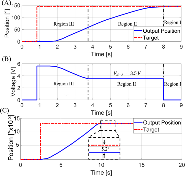
Fig. 5.
(A) The motor’s response to a setpoint of 144° with a resulting steady-state error of 0°. (B) The voltage signal supplied to the motor. The constant voltage in Region II is due to the control-law varying gain used to maintain a voltage level above the dead-band region. (C) The response of the translational motor can also be seen with a less than the characterized value. The resulting 5.2° error can be seen, showcasing the need for using the characterized dead-band voltage.

