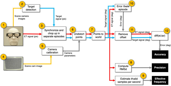
Fig. 4.
From eye tracker signal and scene camera image to data quality measures. (1) The eye tracker delivers scene camera images and an eye tracker signal. This signal contains at least time stamps and a gaze point (x,y) in scene camera image coordinates. (2) Target detection in the scene camera images produces target coordinates (x,y) in scene camera image coordinates. (3) Onset and offsets of the episodes (stand still, walk, skip, jump, and stand still) are manually classified and used to chop up the (target and eye tracker) signals in separate episodes. (4) The scene camera of the eye tracker is equipped with a lens. Lenses may distort the image to a greater or lesser extent. For example, radial distortion causes straight lines in the world to appear curved in the image. For eye trackers, that means that the coordinate system of both the target and gaze coordinates are distorted. A camera calibration can provide us with the parameters to compensate for lens distortions. (6) The camera parameters (produced by 4 and 5) are used to undistort (flatten) the gaze and target coordinates. (7) The gaze and target coordinates are transformed from pixels into unit vectors to enable to report them as directions (in degrees). (8) Precision for each episode is estimated by the sample to sample RMS deviation. (9) We decided not to compute the proportion of data loss, instead we estimated the mean number of valid samples per second and report this as effective frequency. To remove the initial offset (11) from the eye-tracking signal (see bottom panel Fig. 3, the offset is indicated with a yellow arrow), the median signed horizontal and median signed vertical gaze errors (target direction minus gaze direction) obtained during the initial fixate episode (10) were used. (12) Median signed error (accuracy) is calculated for all episodes

