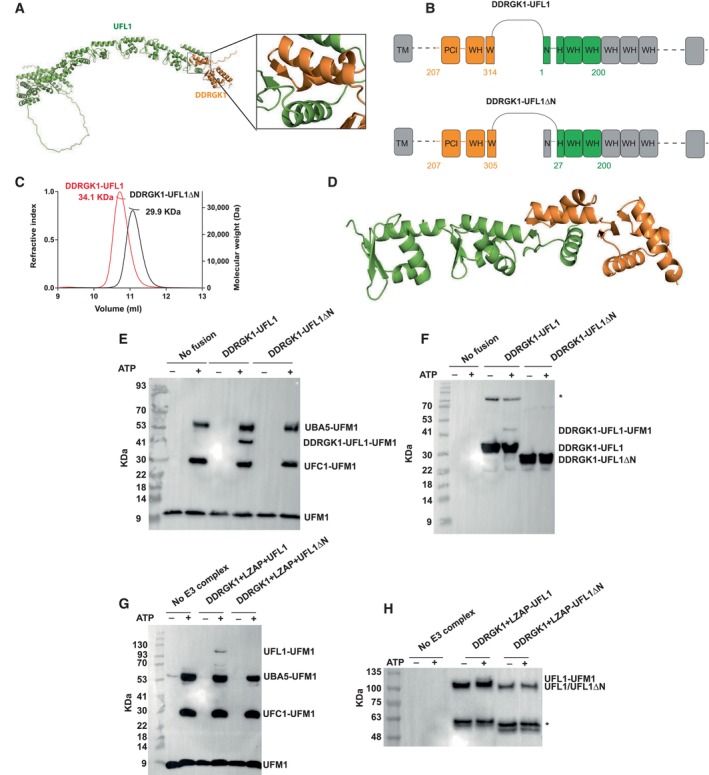
Figure 1. AlphaFold2‐assisted generation of an active fusion protein for ufmylation.

-
AAlphaFold2 structural model of the DDRGK1‐UFL1 complex (the first 206 residues of DDRGK1 are not shown); DDRGK1 is colored in orange; UFL1 colored in green. A blowup shows the winged helix domain shared by DDRGK1 and UFL1.
-
BDetails of the fusion constructs. DDRGK1 was connected to UFL1, removing the N‐terminal region of DDRGK1 and the C‐terminal region of UFL1. In a second construct, we also removed the N‐terminal helix of UFL1 (DDRGK1‐UFL1ΔN), due to its flexibility suggested by AlphaFold2 (see Text). Regions removed from the parent proteins are shown in gray (WH: winged helix domains, PCI: proteasome‐COP9‐initiation factor 3 domain, W and H indicate a partial WH domain).
-
CSEC‐MALS profiles of fusion proteins.
-
DCrystal structure of the DDRGK1‐UFL1ΔN fusion. The four winged helix (WH) domains are colored as in (A).
-
E–HIn vitro ufmylation assays. (E, F) Western blots show that in the presence of DDRGK1‐UFL1 an additional band appears. This band corresponds to ufmylated DDRGK1‐UFL1 and is absent without any fusion protein or in the presence of DDRGK1‐UFL1ΔN (E—blotting with anti‐FLAG, since UFM1 has a FLAG‐tag; F—blotting with anti‐Myc since DDRGK1‐UFL1 has a Myc‐tag); *Indicates nonspecific bands that exist also in the absence of ATP. (G, H) Western blots show a band corresponding to ufmylated UFL1 only in the presence of the ternary complex containing the UFL1 N‐terminus (same corresponding anti‐FLAG and anti‐Myc were used); *Indicates degraded UFL1/UFL1ΔN. See Fig EV1D–H for protein loading controls.
Source data are available online for this figure.
