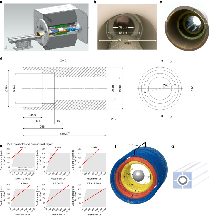
Fig. 1. NexGen 7 T scanner.
a, Cross-sectional rendering of the scanner showing the Impulse gradient coil (green), the receiver–transmit coil connectors attached to the coil interface box with energy chain extending out of the magnet (blue) and a receiver–transmit coil (white) resting on extension of the movable bed (brown). b, Photo of the scanner with the acoustic bore liner giving a 39 cm diameter head region, 56 cm wide shoulder spaces and 60 cm diameter body bore. c, Photograph of the Impulse gradient coil. d, Cross-sectional dimensions of the Impulse gradient coil showing key dimensions (mm). The three coil axes are combined in each of the three layers of windings (primary (Pri.), middle (Mid.), secondary (Sec.)) and the shoulder cutouts are in the y axis middle layer. e, PNS threshold limits in scanner operational region determined by maximum gradient amplitude and rise time (SR) below PNS thresholds. The red line shows the SAFE model threshold31 used during normal scanner operation. f, A 3D layout of the gradient coil showing the three layers of coil winding (primary, middle, secondary). g, Diagrammatic rendering of a segment of the (gray) stainless-steel cooling tubes integrated into conductive windings surrounded by copper filament conductors.

