
Fig 1.
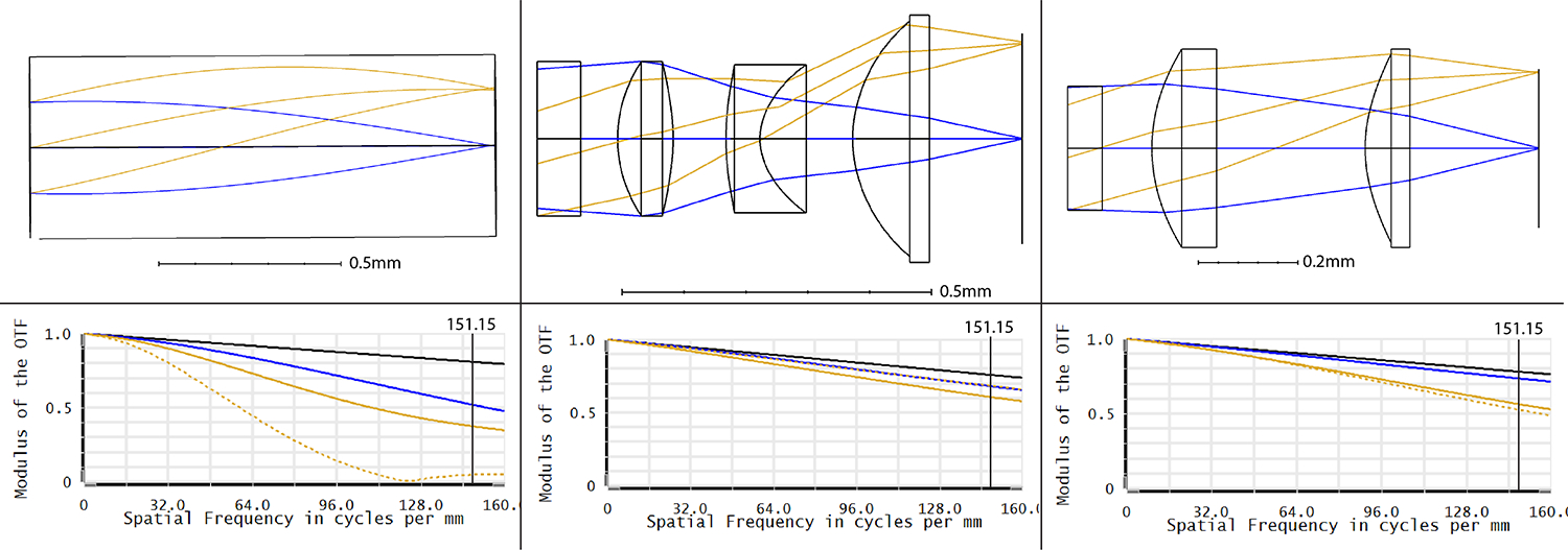
Distal optic layout and modulation transfer functions for (a) GRIN Singlet, (b) 3D printed Doublet, and (c) 3D printed Triplet. The blue lines represent the on-axis field, and the golden rays represent the off-axis field (sagittal rays are represented by the dotted lines, tangential rays by the solid lines). The vertical line on the MTF plots signifies the frequency cutoff imposed by the fiber bundle’s core-to-core spacing (3.3μm) converted to line pairs(lp) per mm (151.2lp/mm).