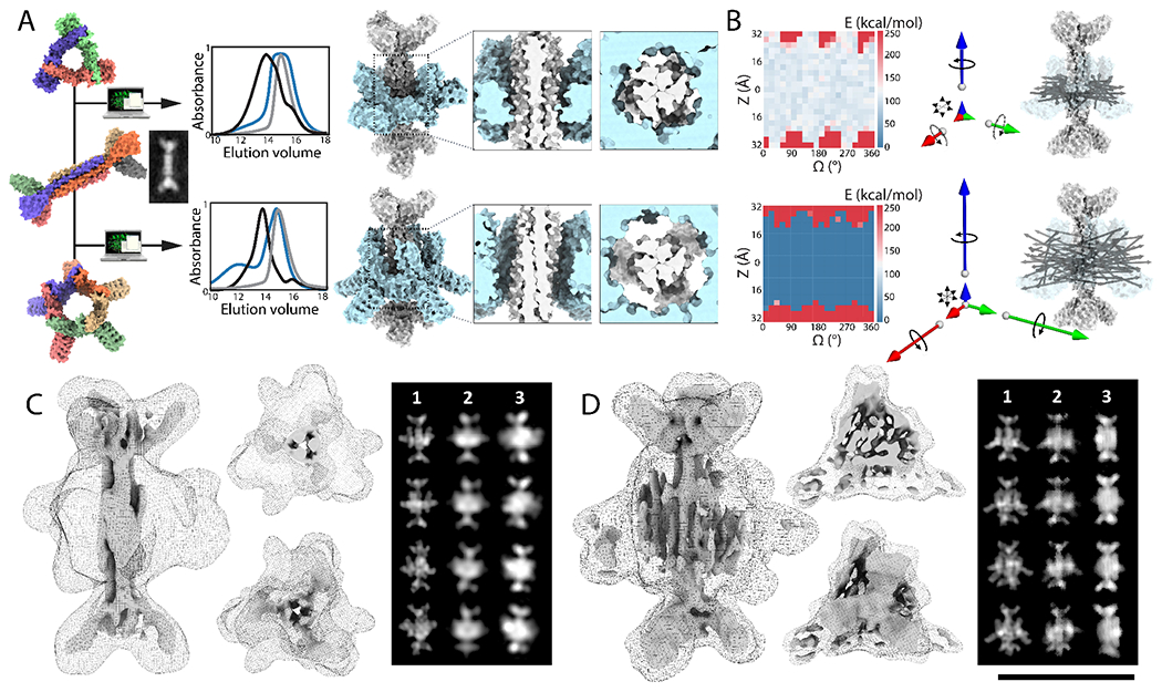
Fig. 3: Design of symmetry mismatched D3-C3 and D3-C5 axle-rotor assemblies.

(A) From Left to right: Models of a D3 axle (D3_3), and C3 (C3_R3) and C5 (C5_2) rotors and cryoEM 2D average of axle alone before assembly. Overlaid SEC chromatograms (absorbance at 215 nm) of axle (grey), rotor (blue), and full assembly (black). Models of D3-C3 and D3-C5 assemblies with top-view and side-view close-up on interfaces: shape and symmetry results in different DOFs. (B) (Left) 2D Rotation-Translation energy landscapes showing a large area of low energy where the rotor can be positioned on the axle (REU: Rosetta Energy Units) (Right) MD simulations results are shown as vectors whose magnitude corresponds to the computed mean square displacement of the rotor relative to the axle along the 6 DOFs. The D3-C3 system is largely constrained to rotation along the z axis (blue), while the D3-C5 assembly allows rotation along x (green), y (red) and z, and translation in z, x and y. N-C termini unit vectors of an ensemble of MD trajectories is superimposed on an axle-rotor model structure. (C) (Left): 3D CryoEM reconstruction of D3-C3, processed in D3 at 7.8Å resolution suggests that the rotor sits midway across the D3 axle consistent with the designed mechanical DOF. The maps are shown as side view, end-on views and transverse slices, as surface for the axle and as mesh for the rotor, at two different thresholds. (Right): simulated 2D class averages without (1) and with (2) conformational variability, and experimental averages (3). (D) (Left) 3D CryoEM reconstruction of D3-C5, processed in C1 at 8.6Å has the overall features of the designed structure, shown as surface and mesh at different thresholds. The 2D averages capture secondary structure corresponding to the C5 rotor, but could not be fully resolved, consistent with the rotor populating conformationally variable states. (Right): simulated 2D class averages without (1) and with (2) conformational variability, and experimental averages (3). Scale bar for cryoEM density: 10nm
