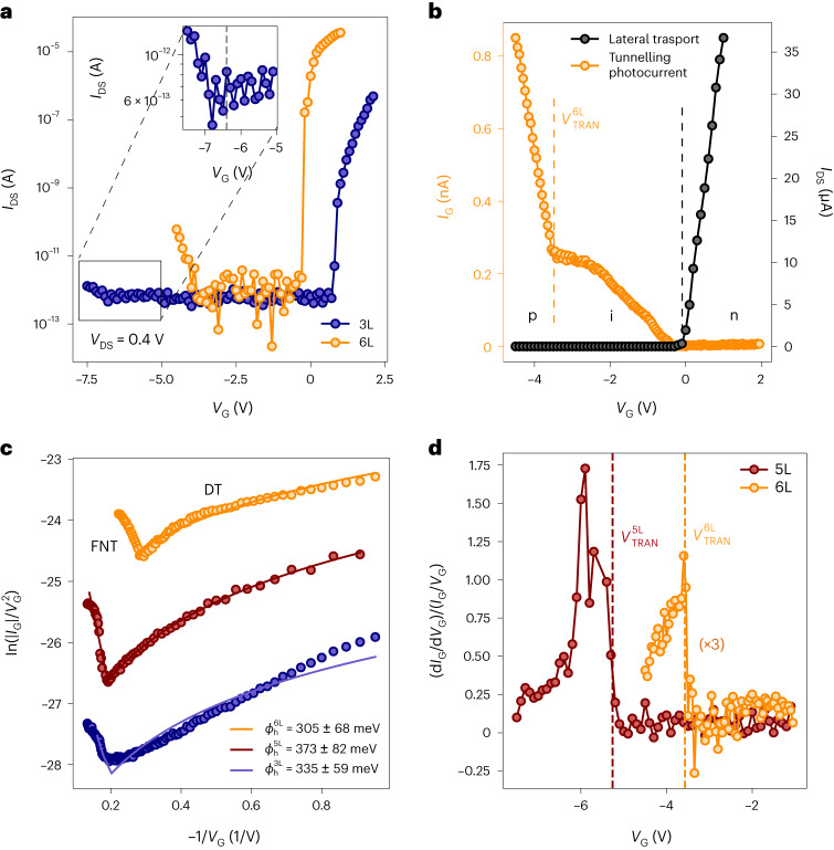
Fig. 2. Field-effect transport and tunnelling photocurrent with few-layer InSe.
a, Field-effect lateral transport in the 3L (measured at 80 mK) and 6L devices in logarithmic scale. Subthreshold p-type conduction was achieved in both samples. Note a lower subthreshold slope in the 3L with respect to the 6L device (Supplementary Note 2). The inset highlights the onset of p-type conduction in the 3L device (). b, The gate-dependent lateral current between the FLG contacts in a 6L device (black) shows predominantly n-type conduction in linear scale. The dashed grey line indicates the onset of n-type conduction. A gate-dependent tunnelling photocurrent is induced when the sample is illuminated using a 633 nm laser at 50 µW of power (yellow). The behaviour of the tunnelling current can be divided into two main regions, which are separated by a yellow dashed line with respect to the gate voltage. c, The gate-dependent tunnelling photocurrent data for 3L, 5L and 6L devices are reported in blue, red and yellow circles, respectively, using the scale with respect to −1/VG for VG < −1 V. The tunnelling behaviour is modelled using Simmons’ approximation, with direct tunneling (DT) and FNT regimes separated by a sharp onset. FNT fittings reveal effective barriers for tunnelling holes of 237, 340 and 292 meV for 3L, 5L and 6L samples, respectively. d, Ratio between the differential conductance and the tunnelling conductance at low temperature for 5L and 6L devices. The weaker 3L signal does not allow us to observe changes in the normalized conductance at cryogenic temperature. Further discussion on the temperature dependence of the dIG/dVG signals is provided in Supplementary Note 3.

