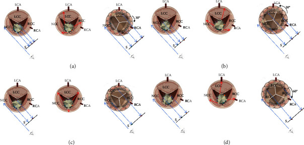
Figure 6.

The three inflow markers on the THV are shown with green, red, and yellow dots. Each panel has three pictures. The first picture shows the position relationship between the THV and the aortic annulus when the THV crosses the aortic annulus. The red arrows in the second picture show the THV commissure moving direction when the THV is deployed. The third picture shows the position relationship between the THV and the aortic annulus after the THV has been deployed. The angulation between the neo-commissure and the native commissure will be 30° clockwise (a) or counter-clockwise (b) when the three markers are separated averagely in the projection with the right and left coronary cusps superimposing. When the centre marker is overlapped with the right one, the angulation between the neo-commissure and the native commissure will be 0° (c). When the centre marker is overlapped with the left one, the angulation between the neo-commissure and the native commissure will be 60°, leading to a total neo-commissural misalignment (d). S = screen; LCA = left coronary artery; RCA = right coronary artery; LCC = left coronary cusp; NCC = noncoronary cusp; RCC = right coronary cusp. The figure was created with biorender.com.
