. 2023 Dec 5;6(1):247–255. doi: 10.1039/d3na00684k

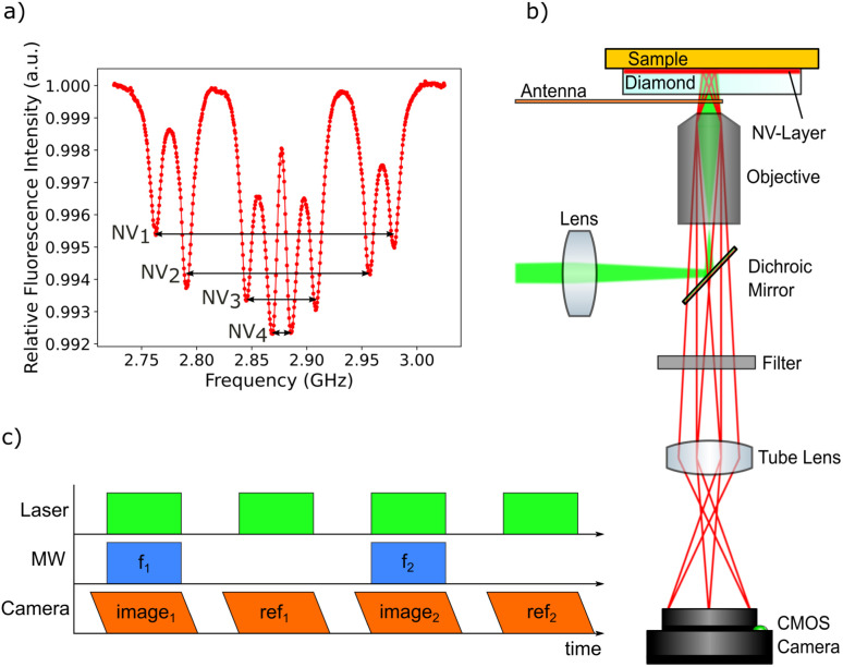
Fig. 3. (a) Average ODMR spectrum of all pixels in the field of view. Four pairs of peaks are visible corresponding to the four NV center orientations within the diamond crystal lattice. A bias magnetic field is applied to split all peaks sufficiently for being able to track all eight peak positions. The peaks are broadened due to the change of the magnetic field over the field of view. (b) Sketch of the widefield NV center magnetometry setup. The excitation laser is reflected by a dichroic mirror and focused on the back focal plane of the objective leading to a collimated laser beam illuminating the NV layer. The sample is placed directly on top of the diamond. The fluorescence light emitted from the NV centers is collected by the objective and imaged on a sCMOS camera sensor. Sweeping the frequency of the microwaves supplied by a loop antenna allows an ODMR spectrum to be recorded for all sensor pixels simultaneously. Background light is eliminated using several filters in front of the camera sensor. (c) The cw-ODMR measurement protocol is build in a way to minimize effects from the camera rolling shutter, which is indicated by the angled sides of the camera frames. For each image, the laser and microwaves are only activated when all pixels are exposed. For each frequency step, a reference image is recorded in order to eliminate low-frequent noise.

Fig. 3