ABSTRACT
We conducted a study to understand the characteristics of the finishing coils to select the appropriate coil for the final stage of embolization. Consequently, experimental embolization was performed on a 10 mm spherical silicone aneurysm filled with radiolucent coils, which simulated a volume embolization ratio of 20%. Nine different coils (i-ED complex ∞ SilkySoft, SilkySoft, ExtraSoft, V-Trak HyperSoft helical, Barricade 10 complex finishing, Optima complex 10 soft, Target 360 Ultra, Galaxy G3 mini, and Axium prime 3D ExtraSoft) were analyzed six times at random. After each coil insertion, indices that include area, Feret diameter, circularity, and centroid center of mass were calculated using biplane x-ray images. Furthermore, these data were analyzed using the spring constant k, which represents the stiffness of the coil. In multiple comparisons, a significant difference was observed in the area analysis. The i-ED complex ∞ SilkySoft was more widespread than Target 360 Ultra (p < 0.05). However, no significant differences were observed in the other indices. The spring constant k value of Target 360 Ultra was 2.5 times larger than that of the i-ED complex ∞ SilkySoft, and it negatively correlated with the area index rather than with the other indices. Notably, it was suggested that the smaller the spring constant k, the wider the distribution of the finishing coils. Although there was little difference between the coils, some coils had characteristics suggesting that good embolization could be expected using appropriate finishing coils.
Key Words: aneurysm, finishing coil, volume embolization ratio, spring constant k
INTRODUCTION
Dense coil packing into the aneurysmal sac is regarded as one of the most important factors in preventing aneurysm recurrence in endovascular coil embolization of intracranial aneurysms.1-3 A high volume embolization ratio (VER) is one of the most objective indicators for estimating embolization success. In addition, selecting appropriate coils is crucial for achieving a high VER. For the final stage of coil embolization, generally very soft coils are selected, and they are often referred to as “finishing coils.”4,5 Recently, various types of finishing coils have been introduced by different companies. Each finishing coil has unique characteristics regarding shape, size, and hardness. Therefore, understanding these characteristic differences is important for performing better coil embolization and achieving a high VER. Endovascular embolization coils have multiple structures, including stock wire, primary wind, and secondary wind.6,7 Although several studies have investigated the characteristics of coils,4-7 the scope of their analysis is currently limited.
Furthermore, finishing coils are commonly used in complex situations. The coils are inserted into the coil mass formed by previously detached coils. Thus, it is challenging to observe the behavior and distribution of the inserted coils in the x-ray images because the radiopaque hamper the visibility of the coils. Therefore, we experimentally used radiolucent coils,5 which have properties similar to those of regular platinum coils. Only the newly inserted coil becomes x-ray opaque with radiolucent coils and can be visualized in an x-ray image. This allows it to be distinguished from previously detached coils.
However, it has been reported that aneurysm diameter greater than 10 mm and VER < 20% are high-risk recurrence factors after endovascular treatment of aneurysms.8 Therefore, this study aimed to examine the various features of finishing coils in a silicone aneurysm model with a diameter of 10 mm and VER of 20%. We believe that the results of this study will help surgeons inexperienced in coil insertion to understand the differences in coil specifications and their effects on coil insertion.
MATERIALS AND METHODS
Aneurysm model and radiolucent coil
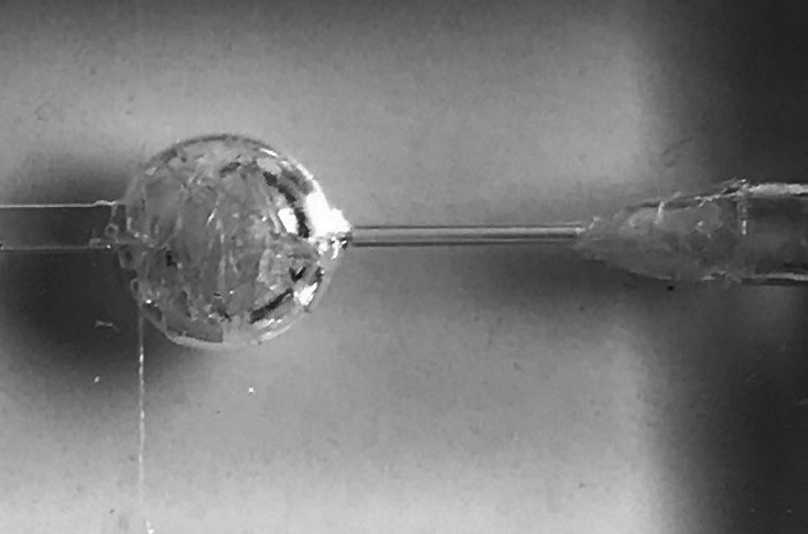
The silicone aneurysm model had a round aneurysm shape. In addition, the dome was 10 mm in diameter, and the neck was 1.0 mm. A metallic coin with a diameter of 1 mm was used as the reference marker. Furthermore, the experimental coils were made of thin nylon thread, which was invisible under fluoroscopy, and were called “radiolucent coils” because of their radiopacity. The aneurysm sac was filled with radiolucent coils to achieve an embolization rate of approximately 20%, assuming the final embolization stage. (Figure 1)
Fig. 1.

The silicone aneurysm model
The dome and neck were 10 mm and 1 mm in diameter, respectively. The experimental coils were made of thin nylon thread, invisible under fluoroscopy, and were referred to as “radiolucent coils” because of their radiopacity. The aneurysm sac was filled with radiolucent coils to achieve an embolization rate of approximately 20%, assuming the final stage of embolization.
Experimental embolization
The experimental embolization was performed under fluoroscopy at a constant speed by a machine because manual coil insertion could have influenced the result. After the microcatheter tip (Excelsior SL-10 STR; Stryker, California, USA) was placed at the center of the aneurysm, each finishing coil was randomly inserted six times. In addition, the insertion speed was established at 1.0 cm/s, and the inserted coil length was 6 cm. Anteroposterior and lateral images were recorded after each coil insertion.
However, nine different coils were made using different stock wire and primary diameters, with a secondary diameter of 3 mm and a length of 6 cm. These were as follows: i-ED complex ∞ SilkySoft, i-ED complex SilkySoft, i-ED complex ExtraSoft (Kaneka Medics, Osaka, Japan), V-Trak HyperSoft helical (Microvention Terumo, California, USA), Barricade 10 complex finishing (Balt, California, USA), Optima complex 10 soft (Balt, California, USA), Target 360 Ultra (Stryker Neurovascular, California, USA), Galaxy G3 mini (J&J, New Jersey, USA), and Axium Prime 3D ExtraSoft (Covidien, California, USA). Furthermore, all coils were three-dimensional except for the HyperSoft helical. The prepared HyperSoft 3D, broke during the first insertion.
Evaluation
Biplane images recorded six times with each coil were analyzed both, anteroposteriorly and laterally. In addition, four indices, including area, Feret diameter (Feret’s D), circularity, and centroid center of mass (CoM), were analyzed using Image analysis software (Image J version 1.52, National Institutes of Health Image, Maryland, USA). The software automatically calculated the above indices after converting the raw images into an 8-bit binary. Furthermore, the area (mm2) was defined as the area surrounded by the outer periphery of the coil, which indicated the frequency of distribution within the rest of the radiolucent coil mass. The Feret’s D (mm) was defined as the maximum diameter of the coil mass. Circularity was defined as a value representing a two-dimensional figure’s complexity. The maximum circularity value for a perfect circle was 1.0, which decreases to 0 as the figure becomes more complex [Circularity = 4π × area / (perimeter)2 ]. Centroid – CoM (mm) was defined as the distance between the center of the area and the center of gravity of the inserted coil mass, which indicated that the coils were distributed unevenly.
Moreover, the data for the above indices were analyzed using the spring constant k,7 which represents the stiffness of the coils and is proportional to the stock wire diameter to the fourth power and inversely proportional to the cube of the primary coil diameter.
Statistical analysis was performed using StatMate version 4.01 (ATMS Corporation, Tokyo, Japan). Kruskal–Wallis test was used to analyze the variance among the nine coil groups, and Dunn’s test was used for multiple comparisons. The relationships between the k values and the four indices were investigated using Spearman’s rank correlation coefficients. Statistical significance was established at p < 0.05.
RESULTS
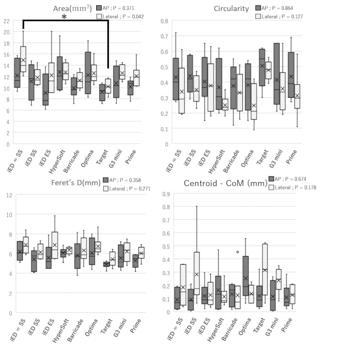
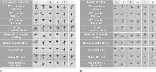
Representative images of each coil are shown in Figures 2A and 2B. The results for the four indices: area, Feret’s D, circularity, and centroid-CoM are shown in Figure 3. In the analysis of the areas, significant differences were observed in multiple comparisons. The coil distribution area ranged from 9.06 to 14.90 mm2. In addition, i-ED complex ∞ SilkySoft had the highest area score, followed by V-Trak HyperSoft helical, Optima complex 10 soft, Galaxy G3 mini, i-ED complex SilkySoft, Axium prime 3D ExtraSoft, i-ED complex ExtraSoft, and Barricade 10 complex finishing, whereas Target 360 Ultra had the lowest area score. A significant difference was observed between the i-ED complex ∞ SilkySoft and Target 360 Ultra in lateral images (p < 0.05). In contrast, no significant differences were observed among the other indices.
Fig. 2.
Representative images of each coil
Fig. 2A: X-ray images after coil insertion in the anteroposterior direction.
Fig. 2B: X-ray images after coil insertion in the lateral direction.
Fig. 3.

Results for the four indices
The box plot of the inserted coils. (horizontal; median, ✗; average) Significant differences were observed in multiple comparisons in the area of the lateral image.
* indicates there was a difference between i-ED complex ∞ SilkySoft and Target 360 ultra in the lateral images (p < 0.050). No significant differences were observed in the other indices.
Feret’s D: Feret’s diameter
CoM: centroid center of mass
AP: anterior-posterior
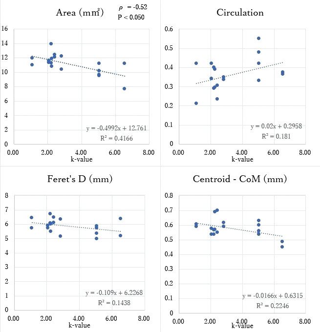
Furthermore, the spring constant k value of Target 360 ultra was 2.5 times larger than that of the i-ED complex ∞ SilkySoft, and negatively correlated with the area index [ρ = –0.52 (p < 0.050)], but no correlation with the other indices [Feret’s D; ρ = –0.31, circularity; ρ = 0.25, centroid – CoM; ρ = –0.23] (Figure 4).
Fig. 4.

Correlation between the four indices and the spring constant k
The spring constant k showed negative correlation with the area index [ρ = –0.52 (p < 0.050)], but no correlation with the other indices [Feret’s D; ρ = –0.31, circularity; ρ = 0.25, centroid – CoM; ρ = –0.23]. The k-value of Target 360 ultra was 2.5 times that of i-ED complex ∞ SilkySoft. The spring constant k was proportional to the stock wire diameter to the fourth power and inversely proportional to the cube of the primary coil diameter, representing the coils’ stiffness.
Feret’s D: Feret’s diameter
CoM: centroid center of mass
DISCUSSION
The selection of appropriate coils is crucial for dense coil packing in endovascular coil embolization of intracranial aneurysms. However, very soft coils are generally selected for the final stage of coil embolization and are often referred to as “finishing coils.” Recently, various types of finishing coils have been introduced by different companies. Silicon aneurysm models filled with radiolucent coils were used to investigate these properties. The experimental model in this study is similar to our previous reports.5 Although the condition of the aneurysm and lineup of the coils are different.
A VER < 20% has been reported to be a high-risk factor for recurrence after endovascular treatment of aneurysms.8 Thus, we established the VER at approximately 20% using radiolucent coils to simulate the final stage of embolization. The procedure was repeated six times individually with nine different coils randomly inserted in the aforementioned spherical silicone aneurysm filled with radiolucent coils. Furthermore, all coils had a secondary diameter of 3 mm and a length of 6 cm. Several studies have reported the relationships between coil insertion speed, insertion force, and friction in the case of first coil placement.9-11 Since we found no impact of coil insertion speed on the end-results, with respect to finishing coils,5 we established the insertion speed at 1.0 cm/s. As no significant change was observed in the external shape of the radiolucent coils after the experiment, we assumed that there was no significant difference between the insertions.
In this study, finishing coils were distributed in 11.5–18.9% of the aneurysm area. A significant difference was observed between the i-ED complex ∞ SilkySoft and Target 360 Ultra in the area of the lateral image (p < 0.05). We collected and evaluated the softest coils in each company’s varieties; however, only Target 360 Ultra was the second softest and may be the hardest too.
In addition, a negative correlation was observed between area and spring constant k,7 and the k value of Target 360 Ultra was 2.5 times larger than that of the i-ED complex ∞ SilkySoft. Therefore, it was suggested that the smaller the stock wire diameter and the larger the primary coil diameter, the smaller the k values and more widely the finishing coils are distributed. This wide distribution characteristic is useful when it is preferred to increase the coil density for sites far from the tip of the catheter where dense embolization is unlikely, but it is accompanied with the disadvantage of the coil tendings to protrude into the parent artery. Thus, it is safer to protect the aneurysm neck with a stent or balloon.
Although no significant differences were observed in the other three indices (Feret’s D, circularity, and centroid – CoM), Feret’s diameter was greater than 3 mm and approximately 6 mm. We assumed that the stiffer the coil, such as Target 360 Ultra, the easier it is to compact it in a smaller shape closer to 3 mm diameter. Therefore, it was proposed that the stiffer the coil (larger k value), the smaller the area it would be distributed over to maintain the secondary diameter.
Similar studies have been conducted previously,5,12 however, we did not find a significant difference in features between coils as we did earlier. This could be because the previous experiment’s image evaluation was only in one direction. In contrast, the present evaluation method involved both anteroposterior and lateral views, additionally the VER of the aneurysm and the variety of coils compared were different from those used previously. Furthermore, many companies are successfully making more flexible finishing coils, which may have made comparing them challenging owing to their similar characteristics.
We firmly believe, similar coils can be compared under similar conditions when a newly manufactured coil is released using our silicon aneurysm model. These results will help inexperienced surgeons in coil insertion as well as to understand the differences in coil specifications and their effects on coil insertion.
LIMITATION
This study had certain limitations. First, the silicone aneurysm used in the experiment had no pulsatile blood flow, and the radiolucent coil was made of a nylon thread. Therefore, their friction may have differed from that observed during the actual coil embolization.
Second, because the conditions for the microcatheter and radiolucent coils were approximately fixed, the position of the microcatheter tip, and the distribution and density of the radiolucent coils may have influenced the finishing coil performance in actual clinical practice. However, the results of this study should be significantly similar to real-world clinical experience. Considering that only a limited number of finishing coils were evaluated in this study, further research with a greater variety of coils (brand, shape, diameter, and length) and aneurysms is needed.
CONCLUSION
After evaluating the characteristics of various finishing coils, significant differences were observed between the i-ED complex ∞ SilkySoft and Target 360 Ultra in the area. It was suggested that the smaller the spring constant k value (the smaller the stock wire diameter and the larger the primary coil diameter), the more widely the finishing coils are distributed. Although a little difference was observed between the coils, some had characteristics suggesting that good embolization could be expected with appropriate finishing coils.
ACKNOWLEDGMENTS
Kaneka Medix supported the development of the radiolucent coil, but the authors independently performed data analyses.
DECLARATION OF CONFLICTION INTERESTS
The authors declare no potential conflicts of interest regarding the research, authorship, or publication of this article.
FUNDING
The authors have no personal or financial interests in any of the materials or devices described in this article.
Abbreviations
- VER
volume embolization ratio
References
- 1.Kawanabe Y, Sadato A, Taki W, Hashimoto N. Endovascular occlusion of intracranial aneurysms with Guglielmi detachable coils: correlation between coil packing ratio and coil compaction. Acta Neurochir(Wien). 2001;143(5):451–455. doi: 10.1007/s007010170073. [DOI] [PubMed]
- 2.Tamatani S, Ito Y, Abe H, Koike T, Takeuchi S, Tanaka R. Evaluation of the stability of aneurysms after embolization using detachable coils: correlation between stability of aneurysms and embolized volume of aneurysms. AJNR Am J Neuroradiol. 2002;23(5):762–767. [PMC free article] [PubMed]
- 3.Sluzewski M, van Rooij WJ, Slob MJ, Bescós JO, Slump CH, Wijnalda D. Relation between aneurysm volume, packing, and compaction in 145 cerebral aneurysms treated with coils. Radiology. 2004;231(3):653–658. doi: 10.1148/radiol.2313030460. [DOI] [PubMed]
- 4.Kanenaka N, Sato H, Hiraoka F, Abe H, Torihashi K, Sora S. Comparative examination of finishing coils available in Japan. J Neuroendovasc Ther. 2016;10(2):88–92. doi: 10.5797/jnet.tn.2015-0003. [DOI]
- 5.Ota K, Matsubara N, Miyachi S, et al. Evaluation of the characteristics of various types of finishing coils for the embolization of intracranial aneurysms in an experimental model with radiolucent coils. Interv Neuroradiol. 2017;23(2):143–150. doi: 10.1177/1591019916685713. [DOI] [PMC free article] [PubMed]
- 6.Ohashi M, Nomura H, Kyoshima K, Nagasawa S, Tsuda E. Aneurysmal wall stress caused by platinum coils is not dependent on the size of a coil but on a diameter of the stock wire: in-vitro study [in Japanese]. J Neuroendovasc Ther. 2013;7(2):81–87. doi: 10.5797/jnet.7.81. [DOI]
- 7.White JB, Ken CG, Cloft HJ, Kallmes DF. Coils in a nutshell: a review of coil physical properties. AJNR Am J Neuroradiol. 2008;29(7):1242–1246. doi: 10.3174/ajnr.A1067. [DOI] [PMC free article] [PubMed]
- 8.Huang DZ, Jiang B, He W, Wang YH, Wang ZG. Risk factors for the recurrence of an intracranial saccular aneurysm following endovascular treatment. Oncotarget. 2017;8(20):33676–33682. doi: 10.18632/oncotarget.16897. [DOI] [PMC free article] [PubMed]
- 9.Matsubara N, Miyachi S, Nagano Y, et al. A novel pressure sensor with an optical system for coil embolization of intracranial aneurysms. Laboratory investigation. J Neurosurg. 2009;111(1):41–47. doi: 10.3171/2009.1.JNS081181. [DOI] [PubMed]
- 10.Harada K, Morioka J. Initial experience with an extremely soft bare platinum coil, ED coil-10 Extra Soft, for endovascular treatment of cerebral aneurysms. J Neurointerv Surg. 2013;5(6):577–581. doi: 10.1136/neurintsurg-2012-010498. [DOI] [PMC free article] [PubMed]
- 11.Lamano JB, Bushnell GG, Chen H, et al. Force characterization of intracranial endovascular embolization: coil type, microcatheter placement, and insertion rate. Neurosurgery. 2014;75(6):707–715;discussion 715–716. doi: 10.1227/NEU.0000000000000525. [DOI] [PMC free article] [PubMed]
- 12.Ito M, Matsubara N, Izumi T, et al. Experimental study of the characteristics of various types of filling coils for intracranial aneurysm embolization. Interv Neuroradiol. 2018;24(5):513–519. doi: 10.1177/1591019918779196. [DOI] [PMC free article] [PubMed]


