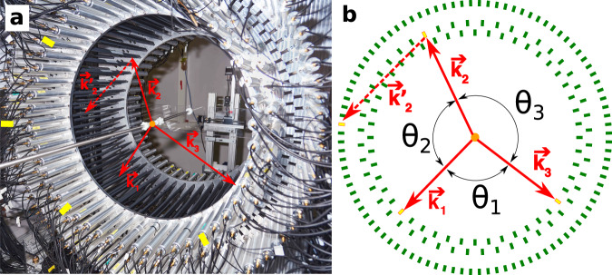
Fig. 1. The J-PET detection system.
The orange dot indicates the position of the sodium source. The superimposed solid red arrows indicate momenta of annihilation photons (k1 > k2 > k3) originating from the decay of ortho-Positronium. The dashed red vector represents the momentum of the secondary scattered photon (). Photomultipliers registering signals from these four photons are marked with yellow rectangles. a Photograph of the J-PET detector with the annihilation chamber installed at the center. Strips of plastic scintillator wrapped in black foil are mounted between two aluminum plates. Photomultipliers reading optical signals from these strips are inserted in aluminum tubes with mu-metal insert for optic and magnetic isolation. b Scheme of the J-PET detector where scintillators are drawn as green rectangles. For every selected event the directions of the momentum vectors for the three annihilation photons are reconstructed between the known position of radioactive source and the reconstructed hit point. Due to momentum conservation these three vectors are co-planar (annihilation plane). In the presented example the photon with medium energy (k2) interacts with the detector material and scatters as (forming the scattering plane). The angles between photon momenta are indicated such as θ1 < θ2 < θ3. Note that ordering of these angles is not directly related to the ordering of the momenta.

