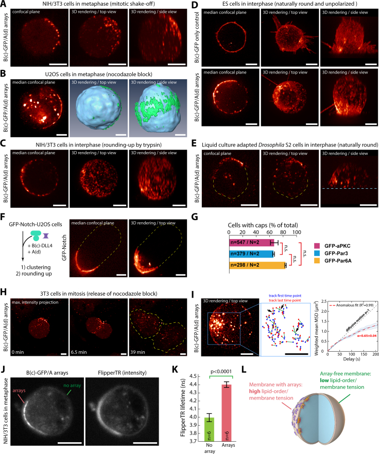
Figure S2.
Induction of cap formation in different rounded cell types, related to Figure 1
(A–C) SDCM images after sequential incubation with B(c)GFP and A(d) for array formation of rounded-up mitotic 3T3 cells co-expressing GBP-TM-GBP and GFP (A), U2OS cells transiently expressing GBP-TM-mScarlet arrested in mitosis using nocodazole block (B), and 3T3 cells expressing GBP-TM-mScarlet in interphase with cell-rounding induced using trypsin (C).
(D) Mouse embryonic stem cells stably expressing GBP-TM-GBP imaged by SDCM after incubation with B(c)GFP followed by A(d) to induce array formation (bottom) or not (top).
(E) Suspension Drosophila S2 cells expressing GBP-TM-GBP after incubation with B(c)GFP followed by A(d) for array formation. SDCM imaging.
(F) Cap formation is not restricted to artificial GBP-TM constructs. SDCM images of arrays assembled at the surface of U2OS cells expressing GFP-Notch by sequential incubation with B(c)-SC:ST-DLL4 (DLL4 is a Notch ligand) and A(d)-GFP.
(G) Efficiency of cap formation, assessed by the percentage of cells with an asymmetric cap after mitotic shake-off, does not significantly depend on the protein of interest targeted to the cap in 3T3 cells co-expressing GBP-TM-GBP and indicated GFP fusion. (Mean ± SD; n = total number of cells scored indicated in each condition; N = number of independent experiments.) Statistics: Kruskal-Wallis test.
(H) Caps are reversible and dissolve upon spreading for adherent cells. Caps were induced at the surface of 3T3 cells co-expressing GBP-TM-GBP and GFP as in (A) followed by stalling in mitosis with 30 nM nocodazole for 12 h. The arrays were then imaged by SDCM upon release of the nocodazole block.
(I) Caps are not formed by a reticulated network of arrays. Caps were induced at the surface of 3T3 cells co-expressing GBP-TM-GBP and GFP-aPKC as in (A), and cells were then stalled in mitosis with 30 nM nocodazole for 12 h. Cells were then imaged by oblique plane light sheet microscopy (left), and arrays were tracked in 3D. Middle: distance traveled by each track plotted as the first (blue dot) and last (red dot) time point. Black arrows indicate events of crossing between tracks marking events when arrays change neighbors. Right: mean square displacement (MSD) analysis of array motion as a function of delay time. The thick blue line corresponds to the weighted mean curve, which weights the MSD curves according to their certainty (lighter area, SEM). Red line: anomalous fit of the weighted mean curve. N = 137 tracks.
(J–L) Array localization correlates with membranes of altered biophysical properties.
(J) 3T3 cells stably expressing GBP-TM-mScarlet with assembled arrays and stalled in mitosis using nocodazole incubated with Flipper-TR probe processed for fluorescence lifetime imaging.
(K) Intensity-weighted average lifetime of the Flipper-TR probe in regions where arrays are present (segmented using GFP fluorescence) or not (mean ± SEM). A higher Flipper-TR lifetime of the probe indicates a local high-order and/or high-tension in the membrane. Statistics: paired Student’s t test (p value indicated; n: number of cells analyzed).
(L) Summary: arrays correlate with regions of higher membrane tension and/or higher lipid packing compared with the surrounding naked membrane. Images in this figure correspond to single confocal planes, 3D reconstruction, or 3D reconstruction with surface rendering as indicated (see STAR Methods).
When necessary, cell contours are indicated in yellow dashed lines and the coverslip in blue dashed lines. Scale bars, 5 μm.

