Figure 1.

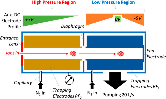
Schematic diagram of the Ion Processor including high-pressure (HP) and low-pressure (LP) regions, auxiliary DC electrode profiles.

Schematic diagram of the Ion Processor including high-pressure (HP) and low-pressure (LP) regions, auxiliary DC electrode profiles.