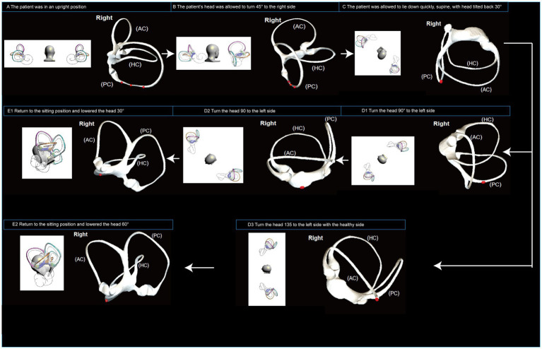
Figure 3.
Operational flowchart of the right Epley maneuver and the modified right Epley maneuver. The left side shows the schematic diagram of the head position and the right side shows the corresponding virtual simulation model of the right semicircular canal. Red dots represent otoliths. AC: anterior semicircular canal; HC: horizontal semicircular canal; PC: posterior semicircular canal.

