Table 3.
Description of FRP manufacturing technologies.
| Process Name |
Process Description | Application | Advantages | Disadvantages |
|---|---|---|---|---|
| Hand lay-up |
It is the simplest and most extensively employed open-mold composite manufacturing method. In this process, fiber preforms are initially positioned within a mold, and a thin layer of an antiadhesive coating is applied to facilitate easy removal. Subsequently, resin material is poured or brushed onto the reinforcement material, and a roller is used to effectively drive the resin into the fabric to enhance interaction between successive layers of the reinforcement and the matrix materials [18]. | Manufacturing large structures in low quantities in the marine sector (boat hulls and related components), automotive industry (such as car body panels), energy field (wind turbine blades), transportation (including large containers), and household applications (swimming pools, bathtubs, etc.) [17]. | Low-cost equipment and operation. Suitable for large components. Adaptability to complex shapes. Environmental sustainability (involves lower energy consumption and fewer emissions compared to some automated processes). |
Due to the open-mold, the products have a single well-finished surface, necessitating a secondary trimming operation [17]. Labor-cost heavy and inefficient [23]. |
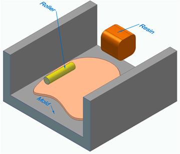 (Adapted form [20]). (Adapted form [20]). | ||||
| Spray lay-up |
The spray-up technique shares similarities with hand lay-up, with the main distinction being the utilization of a spray gun that dispenses resin and chopped fibers onto a mold [18]. | The method is suitable for low and moderate production of large FRP composite structures, such as bathroom units and ventilation hoods [17]. | Simplicity. Faster FRP production and greater shape complexity compared to low-cost hand lay-up technique equipment. |
The parts have only one finished part surface. Resin waste. Reduced fiber orientation control. Air entrapment. |
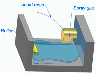 (Adapted form [20]). (Adapted form [20]). | ||||
| Pultrusion | This process involves the continuous pulling or reinforcing of fibers through a resin bath, followed by a shaping die or heated die that cures the composite material. | FRP bars, profiles, and strips [11]. |
This method is simple, effective, and adaptable and represents the most economical solution for producing continuous fiber structural composites characterized by a constant cross-sectional profile [19]. It is suitable for mass production. |
It is less suitable for complex or intricate shapes and components that require varying cross-sectional profiles. It is less suitable for complex or intricate shapes and components that require varying cross-sectional profiles. The cost of the required machinery, dies, and tooling can be significant. It is not economical for unit or batch production [22]. Material waste (trimming and cutting are often necessary to achieve the desired component lengths and shapes). Limited thickness control. |
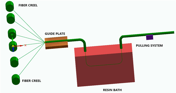 (Adapted form [20]). (Adapted form [20]). | ||||
| Injection molding | In a typical injection molding process, composite fibers in granules/pellets/beads/powder form are introduced through a hopper, and they are then transported through a heated barrel with a screw. Once the necessary amount of material is melted within the barrel, the screw propels it through a nozzle into the mold, where it cools and is obtained the desired shape [18]. | Automotive parts (engine covers, door panels, and lightweight structural components); enclosures for electronic devices and components [18]; medical devices (instrument housings, patient-monitoring equipment, and diagnostic devices). |
High precision. Very low cycle times, enabling the rapid production of parts in high volumes, which is especially advantageous for mass production [18]. Reduced material waste. |
High initial investment due to the specialized equipment and tooling. Complex tooling. Design limitations. FRP parts may require additional finishing or coating processes to achieve a smooth surface finish. |
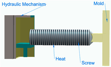 (Adapted form [20]). (Adapted form [20]). | ||||
| Compression molding | It utilizes metal molds, which are preheated within a temperature range of 250 °F to 400 °F and then mounted onto substantial hydraulic or mechanical molding presses. The compression molding process involves placing a resin charge into a mold. One of the mold parts remains fixed, while the other movable mold part applies heat and pressure to shape the material into the desired structure [20]. | The production of high-strength FRP components and high-volume, moderately curved parts across a wide size range (automotive components, aerospace parts, decorative panels, cladding, and architectural elements). | It is a quick and precise method. High productivity. Excellent dimensional stability. The resulting FRP parts feature two exceptionally smooth surfaces and consistent part-to-part quality in comparison to other FRP manufacturing methods like injection molding, resin transfer molding, and vacuum-assisted resin transfer molding. It is one of the most cost-effective molding technologies. It minimizes material waste, making it advantageous for working with high-cost compounds, and it requires minimal post-processing and finishing costs [17]. |
Limitations in producing complex geometries. High tooling costs. Variability in part quality. High energy consumption. Limited automation for complex parts.Challenges in maintaining precise part thickness control. |
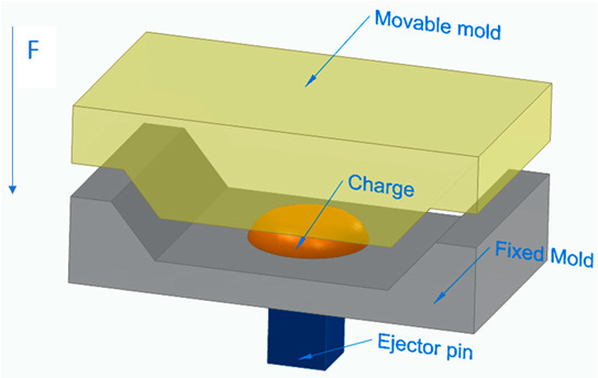 (Adapted form [20]). (Adapted form [20]). | ||||
| Resin transfer molding | In this process, the initial step involves placing a dry fiber preform within the mold cavity. Subsequently, the mold is sealed, and resin is injected under pressure, facilitated by either vacuum or an injection device until the entire cavity is thoroughly saturated with resin. Finally, the resin-impregnated preform is subjected to curing, cooling, and subsequent demolding. | Truck panels, boat hulls, and aerospace and wind turbine blade products [17]. | It allows for the production of components with superior strength and a surface finish that closely replicates the mold’s surface [18]. It allows for flexibility in choosing both the material and its orientation, including the use of 3D reinforcements [20]. Minimum percentage of volatile emissions during processing [17]. |
High tooling costs. Achieving a mold shape that facilitates uniform resin distribution to all parts of the component demands rigorous testing and the application of advanced fluid dynamic simulations. The relatively slow curing time for the parts and the potential for displacement of reinforcement fibers during the resin transfer process [17]. |
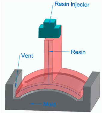 (Adapted form [20]). (Adapted form [20]). | ||||
| Vacuum-assisted resin transfer molding | The process begins with arranging cloth fabrics or fibers into a preform according to the desired configuration. Typically, these fabrics are held together by a binder and pre-compressed to match the mold’s shape. A second matching mold tool is then secured over the first and vacuum-sealed, functioning as a flexible vacuum bag. The next step involves injecting pressurized resin into the mold cavity, assisted by a vacuum. Once impregnation is complete, the FRP composite part is left to cure at room temperature, with optional post-curing [17]. | Aircraft fuselage sections, wind turbine blades, aircraft landing gear doors, large composite panels, and components with minimal void content and a high fiber content [17]. | Adaptable tooling design and material options. Ease of mold geometry adjustments. Capacity to create high-quality, load-bearing, and structurally strong complex structures. It achieves remarkable fiber-to-resin ratios, up to 70%, virtually eliminating void. It uses low injection pressures, typically around 1 atm. |
Fiber misalignment. Voids. Complex mold design. Since only one side of the part comes into contact with the tool, it restricts the attainment of a single smooth surface. The challenge of managing variations in part thickness. |
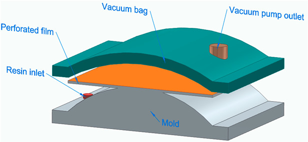 (Adapted form [20]). (Adapted form [20]). | ||||
| Filament winding | It uses a rotating mandrel as the mold. Continuous reinforcement fibers are pulled from roving and guided through a heated resin bath. These resin-infused continuous fibers are then wound around the rotating mandrel, which is shaped internally according to the desired product design [20]. | Cylinders, pipes, bicycles, fuel storage and chemical tanks, stacks, rocket motor cases, pressure vessels, drive shafts, aerospace components, military armaments, power and transmission poles [17]. |
High strength and stiffness because it uses continuous fibers.High strength-to-weight ratio and product uniformity [20]. It allows for the orientation of the direction of the fibers to obtain optimized characteristics [17]. Reduced labor content. |
Limitation in structures with convex shapes. The mandrel is enclosed within the winding, making it challenging to precisely align the fiber along the entire length of the composite and the mandrel. The outer surface of the composite remains unmolded, resulting in an unaesthetic appearance [17]. |
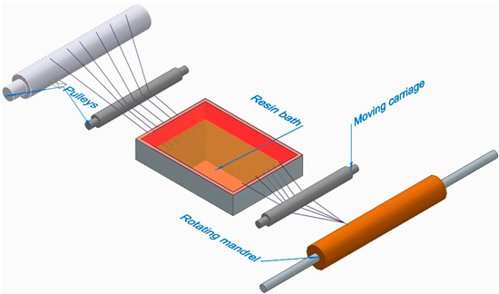 (Adapted form [20]). (Adapted form [20]). | ||||
| Automated tape lay-up (ATL) |
Wide unidirectional tapes are applied to a part of a mold using a roller system equipped with different degrees of articulation, which can vary based on the complexity of the part being produced. Automated tape lay-up essentially imitates the manual process of laying down unidirectional tape but does so at increased speeds [24]. | Large, flat, or single-curvature composite structures [18] | Precision. Reduced labor. Improved material efficiency. It is suitable for larger parts. It offers enhanced process control. |
The cost associated with acquiring the necessary specialized equipment makes the technology inaccessible for small-to-medium-sized manufacturers [18]. Limitations in terms of part complexity. It requires additional training and expertise for operators. |
| Automated fiber placement(AFP) | Fiber-reinforced thermoplastic polymer (FRTP) prepreg tapes are applied to a tool, typically using a robotic arm equipped with a fiber placement head. The feeding unit of the fiber placement head directs the prepreg tapes onto the tool. A heat source warms the tape at the nip point, and a compaction roller presses it onto the substrate during the process. The tape is then sliced into strips of predetermined lengths by a cutting unit. The AFP process is managed by a computer program to arrange the FRTP prepreg tapes in the desired lay-up pattern [25]. | |||
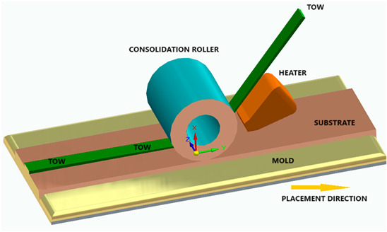 (Adapted form [23]). (Adapted form [23]). | ||||
| Electrospinning | It is an electrostatic fiber fabrication method that uses electrical forces to create continuous fibers ranging from two nanometers to several micrometers in diameter. This process involves expelling a polymer solution through a spinneret, resulting in the formation of a continuous fiber [18], and the fibers are then collected at the apparatus. As a result, it has promising applications in various fields. |
Biomedical sector (wound healing, tissue engineering scaffolds, drug delivery, as a membrane in biosensors, immobilization of enzymes, and cosmetics) [18]. | Improved physical and mechanical properties.Flexibility in controlling process parameters. High surface area-to-volume ratio [18] |
Limited production rate. Challenges in achieving precise fiber diameters. The equipment and associated materials can be expensive. The use of high voltages in the electrospinning process can pose safety risks. |
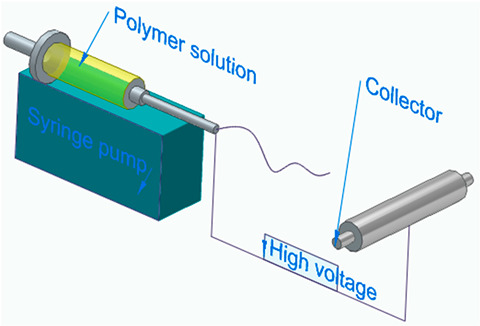 (Adapted form [20]). (Adapted form [20]). | ||||
| Additive manufacturing (AM) |
Additive manufacturing techniques for continuous fiber-reinforced composites encompass methods such as fused deposition modeling (FDM), fused filament fabrication (FFF), directed energy deposition (DED), and laminated object manufacturing (LOM). The most used AM technique is FDM due to some advantages such as simple working principle, low production cost, and efficient and rapid production [23]. | It is particularly valuable in industries where lightweight, strong, and complex components are essential. | High level of geometrical complexity. Computer-aided designing eliminates the necessity of molds, decreasing the cost and manufacturing time. Flexibility in choosing both the volume of fibers and their orientation. Reduces material waste material and cycle time [18]. |
The lack of materials with structural capabilities. The materials presently available generally lack the durability required to serve as a finished product or component. The product size is the print area [26]. |
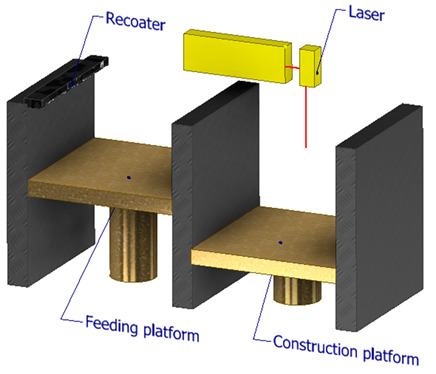 (Adapted form [23]). (Adapted form [23]). | ||||
