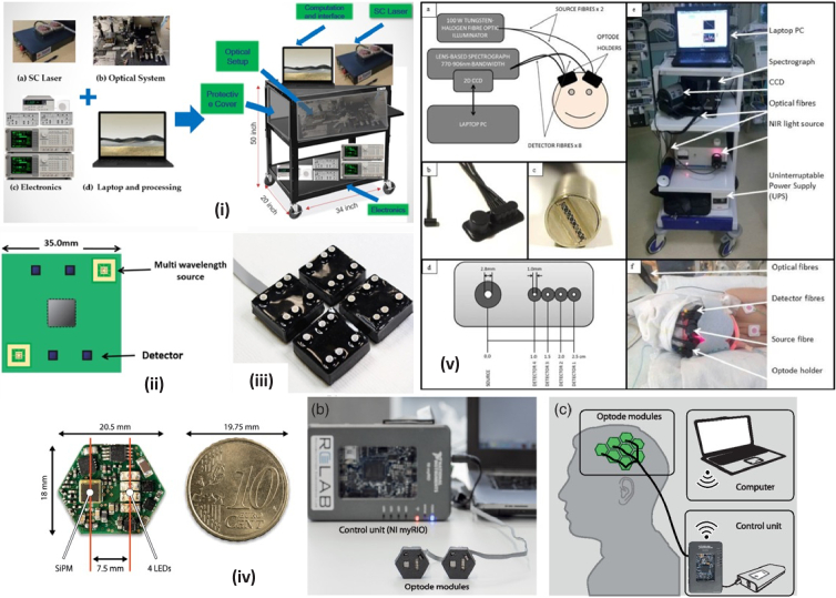
Fig. 5.
Diagram of different systems used in studies included in this review. (i): SCISSCO. High-level system schematic of cart-based SCISSCO prototype [41] , (ii): 8λ UCL. Schematic of single module containing two multi-wavelength sources and four detectors [42], (iii): 8λ UCL. photograph of the four-module system [42], (iv): 4λ Zurich. Visualization of the developed fNIRS instrument. (a) Close-up of the PCB next to a 10-cent euro icon. (b) Picture of the fNIRS instrument with two custom-made optode modules in rapid prototyped casings (front), the control unit, and a PC. (c) Conceptual sketch illustrating the arrangement of the system with eight modules placed over the motor cortex of an adult human. Optode modules are connected to a control unit (NI myRIO and a battery) allowing for wireless communication with a laptop computer [45] . (v): CYRIL. a) Instrumentation diagram with experimental set up. b) Detector optode with optode holder. c) Ferrule of detector fibres for input into spectrograph vertically. d) Optode holder design with dimensions of fibre diameters (all detector fibres have the same diameter) and source-detector distances. e) Image of CYRIL system in NICU. f) Image of CYRIL optodes on a subject [14] .

