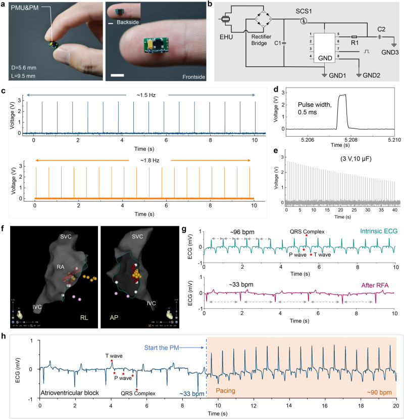
Fig. 3. Characterizations for power management unit & pacemaker module (PMU&PM) of SICP.
a Photographs of the integrated PMU&PM (Scale bar = 5 mm). b Circuit diagram of PMU&PM. c Stimulation pulse generated by PM with different frequencies. d Enlarged view of the stimulation pulse. e PM powered by the capacitor (10 μF, 3 V) that continuously emits stimulating electrical pulses. f Electroanatomic reconstructions of the cardiac structures and ablation target (red dots) by three-dimensional mapping system (superior vena cava (SVC); right atrial (RA); inferior vena cava (IVC); anterior-posterior (AP), right-left (RL) projections). g Electrocardiogram (ECG) before and after construction of an AVB animal model. h ECG of an atrioventricular block (AVB) animal model before and after pacing by PM with a driving voltage of 1.5 V. Source data are provided as a Source Data file.

