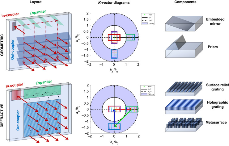
Fig. 1.
Illustration of waveguide combiners. The top row shows a geometric waveguide layout, the corresponding k-vector diagram, and examples of geometric waveguide components. The bottom row shows a diffractive waveguide layout, the corresponding k-vector diagram, and examples of diffractive waveguide components. In the k-vector diagrams, the FOV is shown by the rainbow-colored dots, and the incident FOV on the in-coupler, expander, and out-coupler are highlighted in red, green, and blue boxes, respectively. The purple box in the geometric waveguide shows the out-coupled FOV, which is different from the incident FOV. The red, green, and blue arrows in the diffractive k-vector diagram indicate the grating vectors of the in-coupler, expander, and out-coupler, respectively

