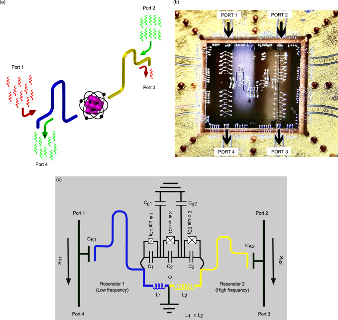
Fig. 1. The studied device.
a Conceptual representation of an artificial atom coupled to two resonators. The photons pass easily from the right side (green arrows, from port 2) to the left side (port 4), whereas those coming from left side (red arrow, from port 1) are mainly reflected back. b Optical microscope image of the device bonded on gold plated copper sample stage. The RF signal enters either via port 1 or port 2. Port 3 and Port 4 are the output ports. The black arrows indicate the direction of signal propagation. c Circuit model of the device. Here, Φ is the external magnetic flux threading through the qubit loop.

