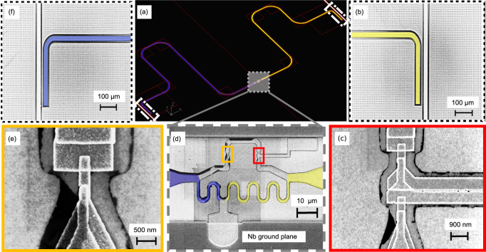
Fig. 2. Electron micrographs of the reported device.
a The CAD layout of the device exhibiting the two resonators and the three-junction superconducting flux qubit at the center. The right and the left resonators are shown by yellow and by dark-blue colors respectively. The areas enclosed with white dotted lines at the top-right and bottom-left corner show the locations of the capacitors coupling the right and the left resonators with the feedlines. In (b, f) we show the magnified images of these capacitors. The gray shaded area close to the center in (a) shows a three-terminal flux qubit. Its zoomed image is shown in (d). The qubit is coupled to both resonators via the local inductances to the left and right, highlighted with different colors. c An enlarged electron micrograph of the two big junctions of the flux qubit. e Electron microscope image of the smaller qubit junction.

