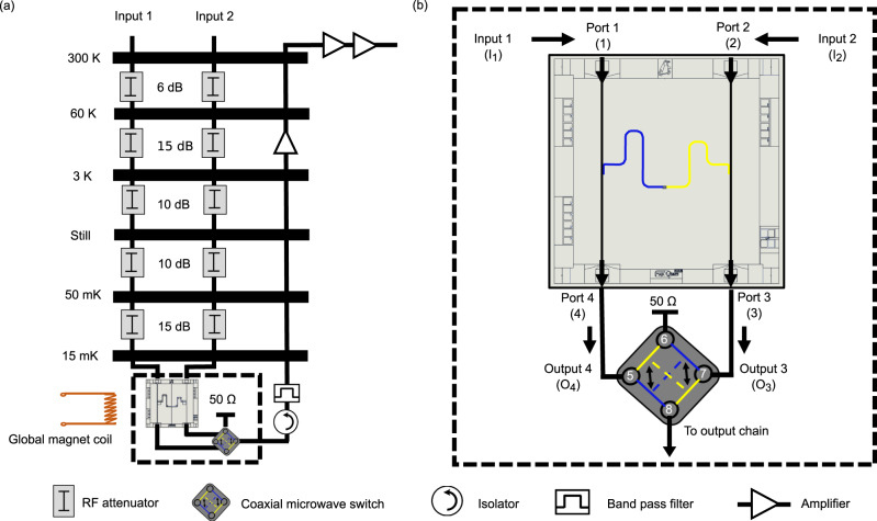
Fig. 3. Measurement setup.
a Different temperature stages of the fridge with respective attenuation at each stage. The attenuation in the input lines 1 and 2 are nominally identical. b An enlarged image of the sample setup at the mixing chamber. Input 1 connects to the port 1 and input 2 --- to the port 2. The output ports 3 and 4 are connected to the coaxial microwave switch (Radiall R577 433002). The employed two-channel (channel A and channel B) switch is driven by a DC (V) bias. The factory defined RF continuity in the employed microwave switch for channel A is 5 → 8 and 7 → 6 (blue color in the switch cartoon), and for channel B is 5 → 6 and 7 → 8 (yellow color in the switch cartoon). It connects one of its input ports (output 4 in the figure) to the output read-out chain, and the same time it terminates the other input (output 3 in the figure) at 50 Ω impedance.

