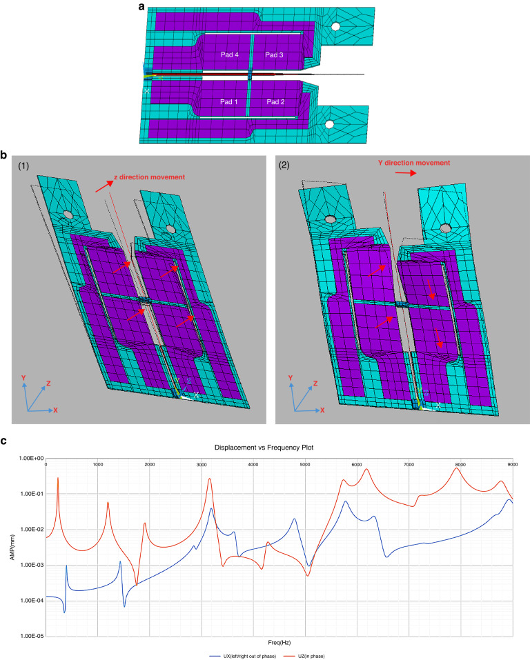
Fig. 2. FEA model of the scanner, showing fiber actuation and simulated fiber tip displacement.
a The FEA model (ANSYS APDL) consisting of substrate (blue), PZT thin film (purple), and tapered optical fiber (red). The boundary conditions are set to 0 displacement and rotation at the left-hand side of the device, and at the mounting holes on the right. b FEA mode shapes showing 2D motion excited by one-dimensional actuation: (1) Vertical fiber motion @ 3189 Hz. (2) Horizontal fiber motion @ 3190 Hz. c Simulated vertical and horizontal displacement from 0–9 kHz with a tapered fiber tip. (Ux: Horizontal, Uz: Vertical displacement)

