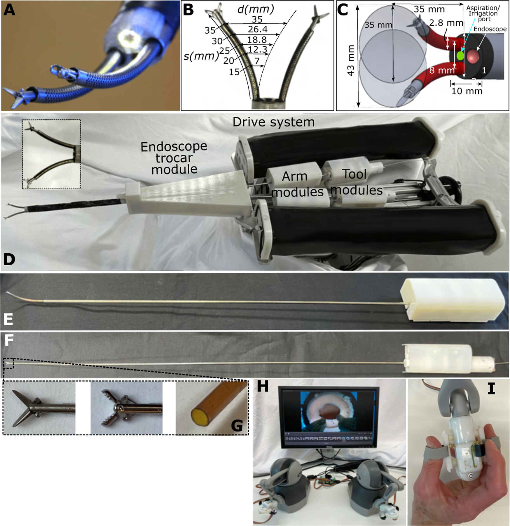
Fig. 2. Neuroendoscopic robot.

(A) Tip of endoscopic trocar showing robotic arms with interchangeable tools. Endoscopic camera is surrounded by LEDs for illumination. (B) Arm workspace diameter, , as a function of arm extension length, , and bending radius of curvature, , where . (C) Schematic showing dimensions of trocar and workspace of arms at full extension. An aspiration/irrigation port is included between the arms. (D) Robot is composed of an endoscopic trocar module, arm modules, tool modules, and a cart-mountable drive system. The system is designed so that a sterile plastic barrier (not shown) can be used to separate all the modules from the drive system (27). In this way, only the modules need to be sterile. Arm modules are inserted through the endoscope module. Tool modules are inserted through the arm modules. All modules are powered by transmission gears, which mate through the sterile barrier, with matching gears in the drive system as shown in fig. S2. (E) Arm module enabling independent rotation of the two precurved NiTi tubes comprising a robotic arm. (F) Tool module that can be changed intraoperatively. (G) Tool tips showing (from left to right) scissors, forceps, and an aspiration/irrigation tool. (H) The surgical console is composed of a computer monitor and two mechanical joysticks. (I) Custom tool controllers enable the surgeon to precisely open and close scissors and forceps. A push button on the controllers pauses and restarts robot motion.
