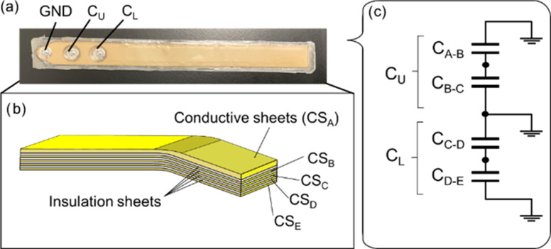
Fig. 1.
(a) Bending angle sensor based on double-layer capacitance. The ground (GND) was established on the left side of the connections. CU was placed at the middle of the connections, and CL was placed at the right of the connections. (b) Diagram of the bending angle sensor based on double-layer capacitance. Each CSs was overlapped via CSA, CSB, CSC, CSD, and CSE. The insulation sheets were sandwiched between each CSs. (c) Electrical schematic of the bending angle sensor based on double-layer capacitance. CU and CL comprise parallel connections of CSA to CSB and CSC to CSD.

