. 2023 Jun 28;4(2):104–114. doi: 10.12336/biomatertransl.2023.02.005

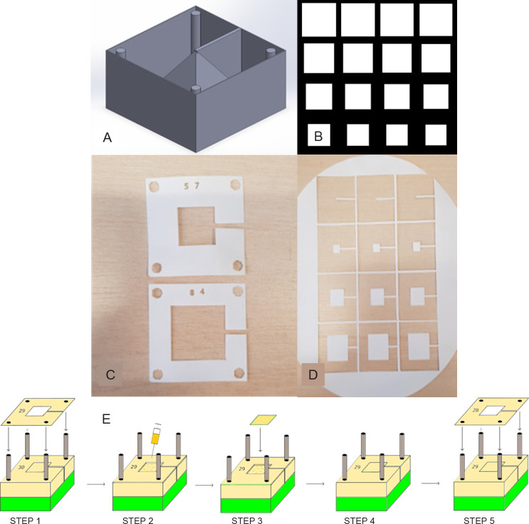
Figure 1. Design and assembly process for fabricating a 3D construct. (A) CAD model with 3D construction and surrounding box and cylinders. (B) Section of the array in InkScape showing different 2D slice shapes used to construct the pyramid. (C) Laser cut alignment slices with an appropriate number designating order. (D) Shape slices on the bulk material to be cross-referenced with alignment slice and placed accordingly on the construct. (E) Schematic of the steps involved in the assembly process, where accurate 3D reconstructions can be created from the 2D slices: Step 1 – placement of alignment slice 29 on the rig using the four holes; Step 2 – Deposition of a couple of drops of alginate solution using a syringe; Steps 3 and 4 – placement of the appropriate shape slice corresponding with alignment slice 29; Step 5 – starting the process again with alignment slice 28. This process continues until all slices are placed. 2D: two-dimensional; 3D: three-dimensional; CAD: computer-aided design. Created with Inventor® Vension 2018.

Figure 1.